
intercom circuit with transistors

To ensure optimal performance and stability in high-gain circuits, the implementation of a dedicated power supply for the speaker is crucial. This approach minimizes the risk of feedback and oscillation, commonly referred to as motor-boating. The design accommodates the integration of multiple stations, enhancing versatility in applications such as audio distribution systems.
The circuit should be housed in two distinct enclosures, each serving as an independent station. This separation not only aids in reducing interference but also facilitates maintenance and troubleshooting. Each enclosure must be equipped with two specific ports: the first is designated for an external power supply, which is preferred over battery power to ensure consistent voltage and current delivery, thereby improving overall circuit stability. The second port serves as a connection point to link additional stations, allowing for a modular setup that can be easily expanded.
Furthermore, the design should include strategically placed holes for a speaker push-on switch. This switch allows for convenient control of the speaker output, enabling users to easily turn the sound on or off as needed. Proper placement of these holes is essential to ensure user accessibility while maintaining the structural integrity of the enclosures.
In conclusion, this circuit design emphasizes the importance of using a separate power supply for the speaker to prevent instability, while also providing flexibility for connecting multiple stations. The careful construction of the enclosures and the inclusion of necessary ports and switches contribute to a robust and user-friendly audio system.The secret to preventing instability (motor-boating) with a high gain circuit like this is to power the speaker from a separate power supply! You can connect an extra station (or two extra stations) to this circuit design. Build the circuit into two separated boxes (for 2 stations). On each box should be use 2 ports for external power supply port (if you use external power supply, not battery) and connection port to other stations. Create some holes for speaker push on switch. 🔗 External reference
Related Circuits
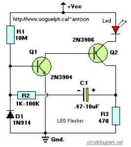
This circuit is designed to flash a high-brightness red LED (5000 mcd), making it suitable for use in fake car alarms or other devices intended to attract attention. The specific values of the components are not critical, allowing for...
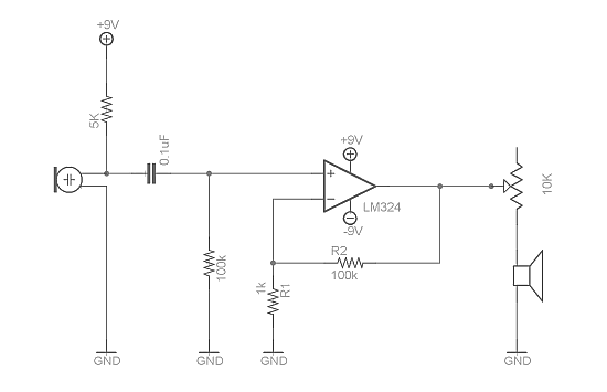
Afroman discusses the fundamentals of utilizing an operational amplifier to amplify small voltage signals and constructs a circuit designed to detect very faint sounds using a microphone. For further details about amplifiers, it is recommended to search for inverting...
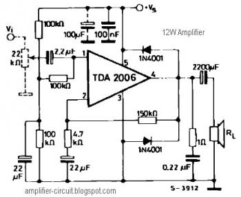
The power amplifier IC TDA2006 provides high output current and has very low harmonic and cross-over distortion. Furthermore, the device incorporates an original (and patented) short circuit protection system that automatically limits the dissipated power to keep the working...
This is a simple and cost-effective inverter designed to power a small soldering iron (25W, 35W, etc.) when a mains supply is not available. The circuit utilizes eight transistors along with several resistors and capacitors. Transistors Q1 and Q2,...

Power-saving electronic mousetrap. This example describes the minimal power consumption, which only occurs when a mouse enters the control zone during foraging activities. After a 30-second delay, the system enters a wait state, making it suitable for outdoor use....

When the water boils, it not only triggers the police but also cuts off the heater power. A temperature sensing element is integrated with a fluorescent neon light bulb, which is restructured within the starter. The described circuit features a...