
Clap Sensitive On-Off Relay

This circuit utilizes a microphone as a sound sensor to detect the sound of a hand clap. The microphone converts the sound waves into an electrical signal, which is then processed by a signal conditioning circuit. This circuit typically includes an amplifier to boost the microphone's output and a comparator to differentiate between the noise level and the clap sound.
The output from the comparator triggers a flip-flop or a microcontroller, which toggles the state of the relay. The relay acts as a switch to control a larger load, allowing for various applications such as lighting or other electronic devices. When the first clap is detected, the relay is activated, and when another clap is detected, the relay is deactivated, creating a simple on/off control mechanism.
Powering the circuit with a 3V battery ensures portability and ease of use. Components such as resistors, capacitors, and possibly a diode for flyback protection may be included in the design to ensure stable operation and protect the circuit from voltage spikes generated by the relay.
Overall, this hand clap relay circuit is an efficient solution for applications requiring remote control without physical switches, providing an innovative and user-friendly interface for electronic device management.3V Battery operated, Small portable unit This circuit was intended to activate a relay by means of a hand clap. Further claps will turn-off the relay. An.. 🔗 External reference
Related Circuits
The provided schematic diagram illustrates an LM741 light/dark sensor circuit, derived from the 741 Op-Amp Tutorial by Tony van Roon. The ECG128/NTE128 transistor can be replaced with any NPN transistor that meets the necessary gain and current specifications for...

Here is a simple thermostat circuit that can be used to control a relay and supply power to a small space heater through the relay contacts. The relay contacts should be rated above the current requirements for the heater....
This circuit is an ultra-sensitive infrared (IR) receiver designed to control various AC devices via an IR transmitter. It utilizes a phototransistor... The ultra-sensitive IR receiver circuit is engineered to detect infrared signals emitted from an IR transmitter, enabling the...
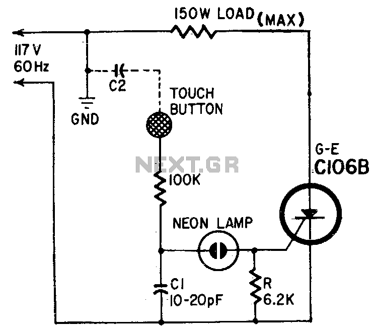
Capacitor Cl and body capacitance (C2) of the operator form a voltage divider from the hot side of the AC line to ground. The voltage across Cl is determined by the ratio of Cl to C2. A higher voltage...

The relay power in the linear circuit is derived from a -120 V bias supply, while the transmit keying output from the Kenwood device is +12 V with a maximum current of 10 mA. A critical component of this...
This article aims to utilize an old PC as a simple controller. Many outdated PCs, such as the 8088, 8086, 80286, 80386, or even 80486, have become obsolete systems. This design employs an 8-bit LPT printer parallel data port...