
interleaving good boost converters too

The multiphase technique involves the use of multiple phases in power conversion circuits, which allows for the distribution of current across several inductors and capacitors. This distribution leads to a reduction in the overall ripple voltage, as the output current is smoothed out over the multiple phases. In a typical multiphase boost converter, each phase operates in a synchronized manner, sharing the load equally, which results in lower stress on individual components and improved thermal performance.
By employing a multiphase topology, the size of passive components can be significantly reduced. Smaller inductors and capacitors can be used without compromising performance, as the effective current handling capability increases with the number of phases. This reduction in component size not only saves board space but also enhances the overall reliability of the circuit.
Furthermore, the multiphase approach can improve transient response. When there is a sudden change in load, the multiple phases can respond more quickly than a single-phase converter, ensuring stable output voltage and current. This characteristic is particularly beneficial in applications where load conditions fluctuate rapidly.
In summary, the multiphase approach is a valuable strategy in the design of boost converters, providing enhanced efficiency, reduced ripple, and smaller component sizes, while also improving transient response and overall circuit performance.Long used to improve efficiency, reduce ripple, and shrink capacitor and inductor size in buck converters, the multiphase approach can provide the same benefits for boost converters.. 🔗 External reference
Related Circuits
A discussion took place on synth-diy regarding the challenges of constructing a voltage-controlled oscillator with a sawtooth wave output, where the duty cycle (the ratio of ramp-up time to ramp-down time) can be adjusted using a separate control voltage....
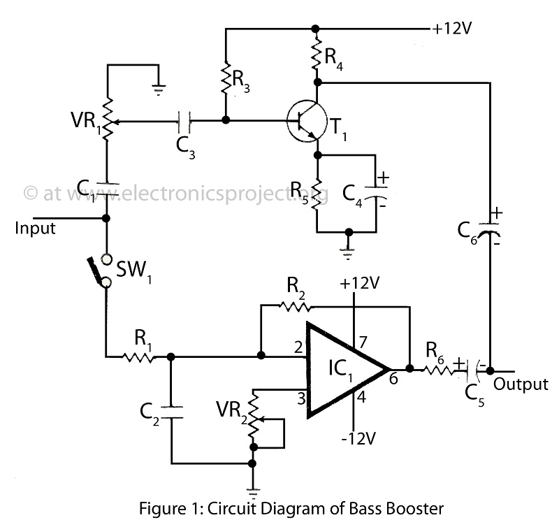
The bass booster featured on this website enhances the beat frequency while maintaining the integrity of the high-frequency response. The circuit diagram for the bass booster, along with various radio circuits, is also provided. The bass booster circuit operates by...

This is a design for a sawtooth generator circuit. The advantage of this circuit is its low cost and the capability to produce an auxiliary square wave at the same frequency. This circuit can be utilized to sweep the...
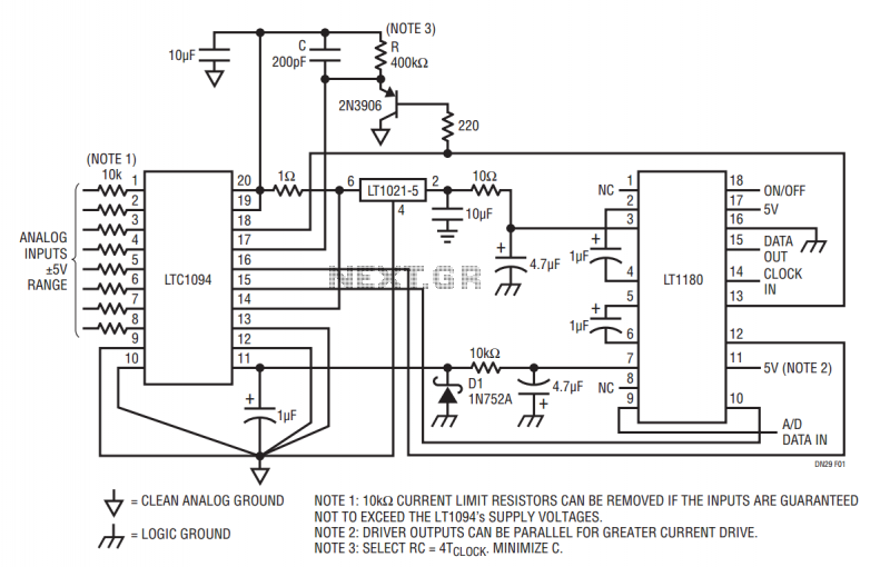
The LT1180 RS232 transceiver includes a charge pump which produces low ripple supplies with sufficient surplus current to drive a CMOS A to D converter and precision voltage reference. The circuit operates from a single 5V supply and draws...
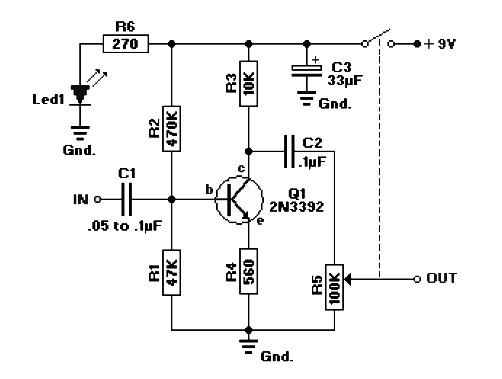
The circuit diagram represents a booster for an audio application. It features a linear potentiometer R5 with a resistance of 100K ohms, which includes an on/off switch. The capacitor C1 should be selected with a value between 0.05 µF...
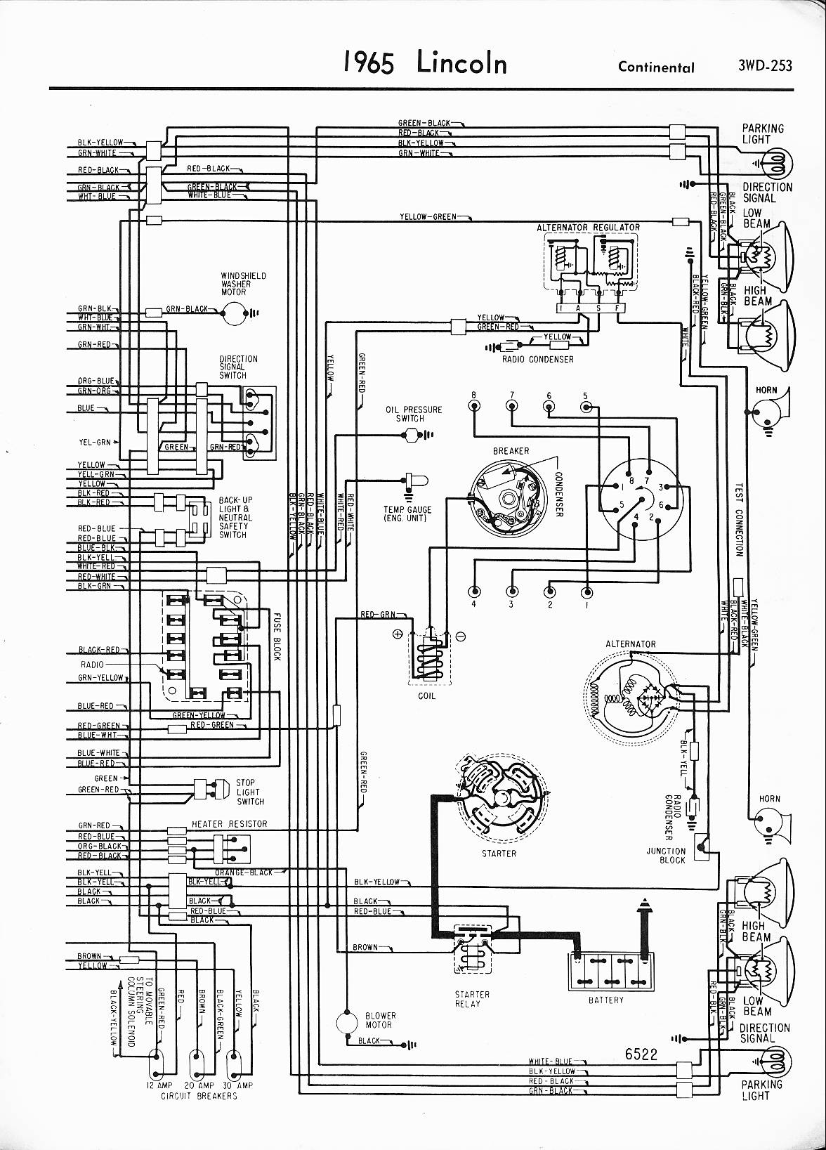
A 1971 Lincoln Continental 4-door is experiencing a complete power failure inside the vehicle, particularly affecting the ignition switch. The battery cables, post connectors, and fusible link have been checked and are functioning correctly. All fuses in the fuse...