
BC 109C For Tone Control

The BC 109C transistor is a versatile component often utilized in audio applications, particularly in tone control circuits. This circuit typically aims to adjust the tonal quality of audio signals by modifying frequency response characteristics. The configuration may involve a combination of resistors and capacitors arranged to form high-pass and low-pass filters, allowing for selective attenuation of specific frequency ranges.
In a typical tone control circuit utilizing the BC 109C, the high input impedance is crucial as it ensures minimal loading on the preceding stages of the audio signal chain. This characteristic allows the circuit to maintain signal integrity, preserving the quality of the audio signal being processed.
The circuit may employ a potentiometer to provide variable control over the tone adjustments, enabling users to boost or cut bass and treble frequencies according to their preferences. The output of the tone control circuit can be fed into a power amplifier or other audio processing units, where the adjusted audio signal can be further manipulated or amplified.
Overall, the BC 109C tone control circuit is designed to enhance audio playback by offering users the ability to tailor sound characteristics to their liking while ensuring high fidelity and performance.The following circuit shows about BC 109C For Tone Control Circuit Diagram. Features: all audio frequencies are attenuated,high input impedance, .. 🔗 External reference
Related Circuits
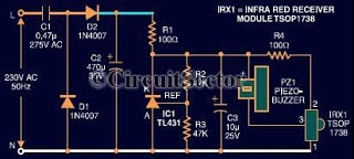
This document presents an infrared remote control tester circuit that can be constructed at a low cost. The circuit is built around the infrared receiver module TSOP1738. The state of the remote control can be observed through the sound...
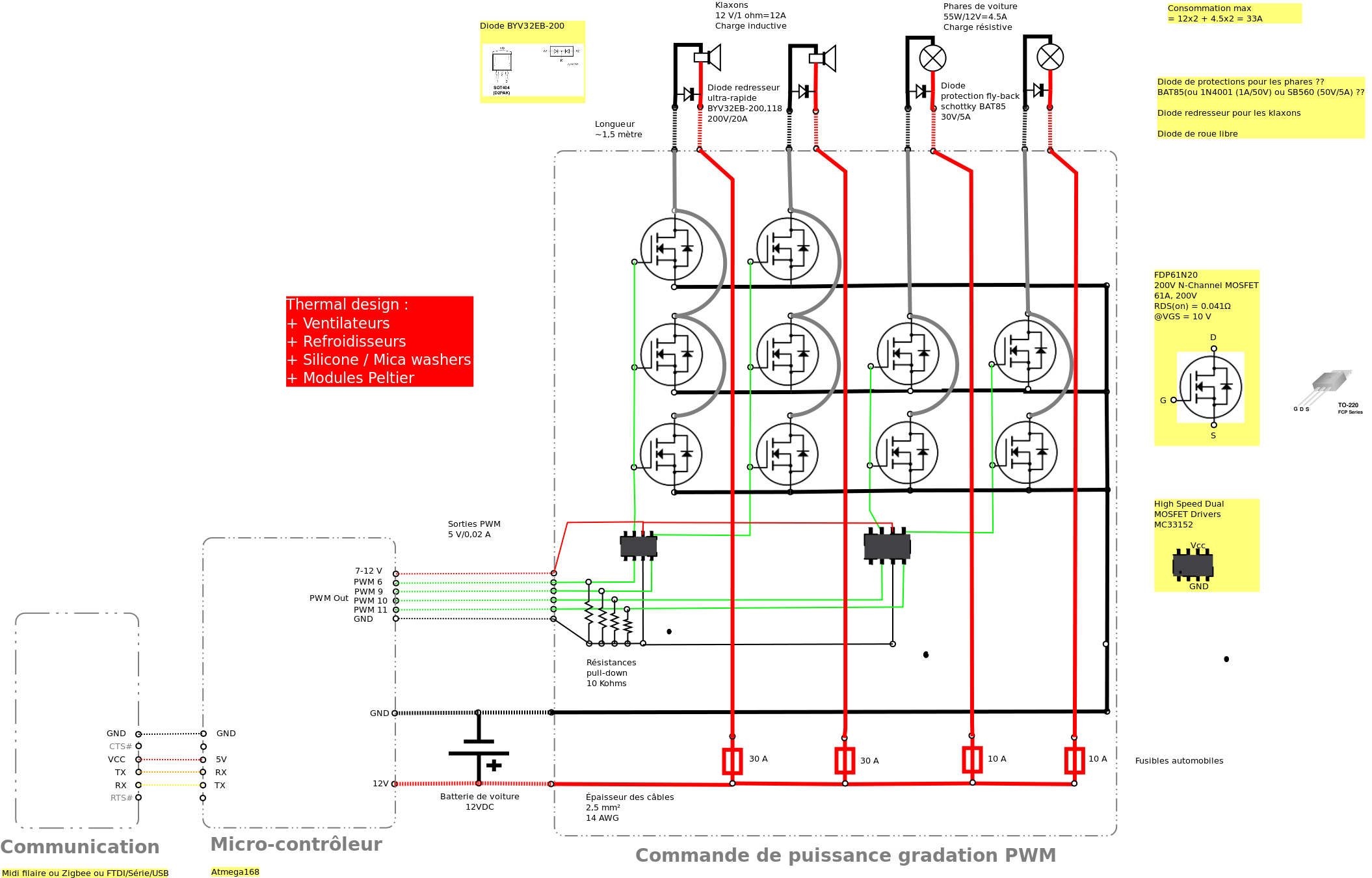
Past experiences were quite challenging due to the inductive nature of car horns, which require 12A of current, with peak demands reaching 20 to 30A. The current electronic system lacks reliability, given the high intensity. There is a need...
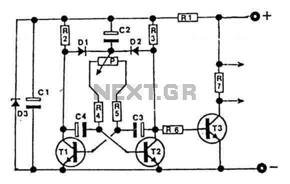
This circuit is designed for controlling motors, lamps, heating elements, and similar devices continuously from nearly zero to maximum capacity (5-95%). It utilizes impulse control for nearly lossless operation, providing almost total torque for motors. The transistor T3 must...
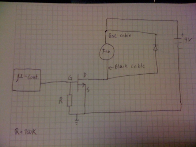
Control a fan using an LM34 temperature sensor and a computer fan with model number ASB0912L. A 2N7000 MOSFET transistor is utilized as a switch. The fan is intended to operate at a 35% duty cycle when the temperature...
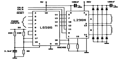
The following figure illustrates the control circuit for a two-phase bipolar stepper motor utilizing the current controller L6506. The L6506 integrated circuit generates the necessary signals to drive the inputs of the L298 bipolar stepper motor circuit driver. The circuit...
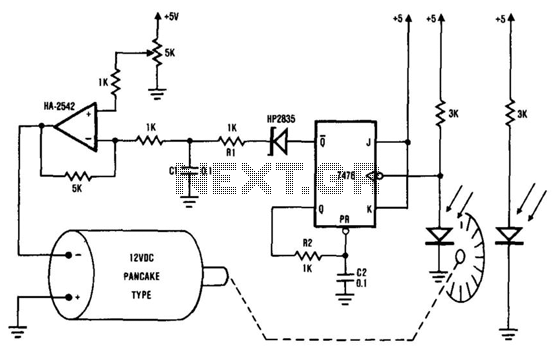
The system comprises the HA-2542 operational amplifier, a compact 12 V DC motor, and a position encoder. During operation, the encoder generates a series of constant-width pulses that charge capacitor C1. These integrated pulses create a reference voltage proportional...