
iPod/MP3 Mini Speaker System

The amplifier in this system amplifies electrical signals, making them stronger and louder. It enables the use of higher resistance speakers by boosting the audio signal. This solid-state, high-gain amplifier design is intended for use with an 8-ohm speaker and was originally designed by Ed Vogel and Blind Lightnin' Pete from MAKE Magazine.
Before assembling the circuit, it is crucial to understand the layout of the protoboard. The board consists of four columns, with the outer two columns connected in rows and the inner two columns also connected in rows. Care must be taken to ensure that the IC DIP socket is positioned correctly, with its pins aligned with the columns to avoid incorrect connections that could prevent the circuit from functioning.
To facilitate assembly, it is recommended to build the circuit pin by pin, starting with pin 2 of the IC DIP socket, followed by the subsequent pins. Organizing the circuit can simplify the construction process; labeling the outer columns of the last two rows as negative and the inner columns as positive can streamline connections to the battery. The positive terminal can be connected to the designated area for +9V, while the negative terminal can be connected to the area designated for ground.
Attention should be given to the output lead connected to pin 5 of the circuit and to the switch connected to pin 6. The switch completes or disconnects the circuit and should not be soldered until later assembly into the enclosure. Once the amplifier circuit is constructed and connected to an 8-ohm speaker, sound playback can commence.
To enhance sound quality, incorporating a filter circuit can be beneficial. A filter circuit, also referred to as a crossover, divides the audio signal into different frequency ranges, allowing the speaker to handle a narrower range of frequencies more efficiently. This results in improved audio clarity and performance.
In summary, the mini speaker system project serves as an educational platform for understanding basic electronic circuits, with practical applications in music playback. It combines an amplifier and filter circuit in a user-friendly design, making it accessible for beginners and electronics enthusiasts alike.Listen and share your music wherever you go With the mini speaker system project, you can listen to music whenever you want: your dorm, your cubicle, or at the beach. This is a great introduction to circuit systems, featuring an introductory amplifier circuit, a filter circuit, and a simple enclosure.
When you`re done, all you need to do is add a 9V battery, plug in and play! The Amplifier In audio terms an amplifier does exactly what its name suggests: it amplifies the current. That is, it takes an electrical signal and makes the signal stronger, and in the end, louder. An electrical signal that is passed by an amplifier comes out louder through the speaker than one that hasn`t been amplified.
Also, because the signal is strengthened by an amplifier, you can play that music through higher resistant speakers. This amplifier is a solid-state-hi-gain design and is intended to run through an 8 ohm speaker. As the amplifier schematic was originally designed by Ed Vogel & Blind Lightnin` Pete from MAKE Magazine, all credit goes to them for the amplifier design.
Before we begin to build the circuit for the amplifier, let`s take a look at the protoboard. This board has a specific layout that should be understood before beginning to solder (unless you enjoy desoldering). The topology of this board is such that there are four columns in which the outer two columns are connected in rows, and the inner two columns are connected in rows.
This should be taken into account when building the circuit. Place solder on the IC DIP socket in a way that none of the rows are connecting. This means that you need to place the IC DIP socket so that the pins are parallel with the columns and the IC DIP socket crosses the gap between one of the outer and inner rows. Also note at which end pin 1 will be located. If you don`t do this your circuit may not work, due to putting the op amp in backwards. Begin to build the circuit as described in the schematic. One trick I found particularly helpful was to make the circuit pin by pin. That is, I worked on the circuitry connected to pin 2 of the IC DIP socket, and then pin 3 and 4 then 5 etc.
Before I began constructing the rest of the circuit, I wanted to do some organization to make the rest of the circuit much easier. I labeled the outer columns of the last two rows (and soldered them together) as negative and the inner columns of the last two rows as positive.
Then I attached the corresponding battery leads to these areas. This way, whenever something needs to be connected to +9V I will hook it up to the `+` area and whenever something needs to be connected to -9V (including anything that needs to be grounded as the -9V will serve as a ground in this circuit), it will simply be hooked up to the `-` area. This method of organization works well for me, you may have another way that works too! Work on pin 5 of the circuit. The wire that is coming from the circuit is the output lead. Also important to note is that it is connected to the center pin of the rheostat. Work on pin 6 of the circuit. It is important to note that the switch is connected to the `+` area and the other to the `+` end of the capacitor.
The end doesn`t particularly matter because a switch merely completes/disconnects a circuit. For now, don`t solder the leads to the switch, as you will need to screw them into the box later. What I did was tie the wire to each end of the switch so that I can remove them later. At this point, we`ve constructed an amplifier circuit. If we hook up an 8 © speaker, we can blast some awesome tunes through it. However, we could do better One way to increase the quality of sound through a speaker system is by utilizing a filter circuit. A filter circuit (also known as a crossover) basically splits up a signal into ranges of frequencies.
This way a speaker would only have to play a smaller range of frequencie 🔗 External reference
Related Circuits
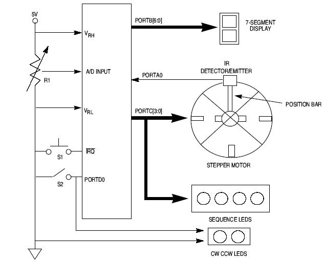
This article explains how to design a stepper motor system using an 8-bit Freescale microcontroller - MC68HC11E9. The design of a stepper motor system utilizing the 8-bit Freescale microcontroller MC68HC11E9 involves several key components and considerations to ensure effective control...
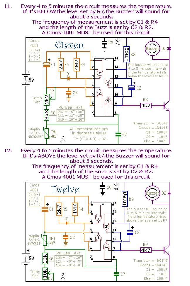
This is a selection of small self-contained alarm circuits. They have a very low standby current; and are suitable for battery operation. The described alarm circuits are compact and designed for low power consumption, making them ideal for battery-powered applications....
The unit is powered directly from the 120 volt AC line, with no power transformers. Filaments are wired in series, with the total adding up to 117 volts (35 + 35 + 35 + 12). The 35W4 forms a...
The YouTube video below demonstrates the quick and easy setup of the system at the launch site. The provided description indicates a focus on the efficiency of system installation at a launch site, as showcased in a YouTube video. In...

The phase and neutral wires from the power source have already been connected to electrical appliances such as fans and light points. According to the UPS connection diagram, an additional phase wire should be connected to those appliances where...
A micro power supply unit (PSU) is designed to power a breadboard with a voltage output of 5 volts. It can be connected to a 9V battery, a 12V source, or any other direct current (DC) power supply ranging...