
Ir Heat-Controlled Kitchen Fan

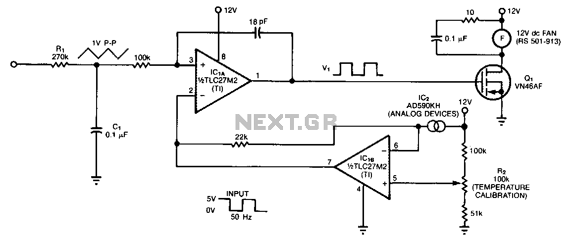
The circuit operates by utilizing an infrared (IR) sensor, designated as Q1, which detects the presence of heat sources. Upon detecting IR radiation, Q1 generates an output signal that activates the control circuit. The component U1 serves as a switching device, which, when energized by Q1, allows current to flow to the optocoupler U1. The optocoupler is critical for isolating the control side of the circuit from the high-voltage side, ensuring safety and preventing damage to sensitive components.
Once the optocoupler is activated, it sends a signal to TRIAC TR1. The TRIAC functions as a switch that can control the power delivered to the fan. When TR1 is triggered, it allows current to flow through the fan, activating it and providing cooling as needed. The choice of TRIAC is essential; a suitable component, such as a 200-V, 6-A TRIAC (C106B) or similar from Radio Shack, is recommended for this application to ensure it can handle the power requirements of the fan.
This circuit design is efficient for applications where automated cooling is required in response to heat detection, such as in HVAC systems or electronic device cooling solutions. The use of an optocoupler not only provides isolation but also enhances the reliability of the system by protecting the low-voltage control circuitry from high-voltage spikes that may occur when the TRIAC is activated. Overall, this combination of components creates a robust solution for controlling fan operation based on thermal input. Ql senses IR from heat sources, causes U1 to switch, activates optocopuler Ul, and triggers TR1. This contro ls a fan. The Triac is from Radio Shack, or else a 200-V, 6-A unit (C106B) can be used.
Related Circuits
An Arduino is used to measure the rotational speed of a basic computer fan. This project was part of a series of YouTube videos created during a Master's program in Computer Science, specifically focusing on an embedded systems programming...
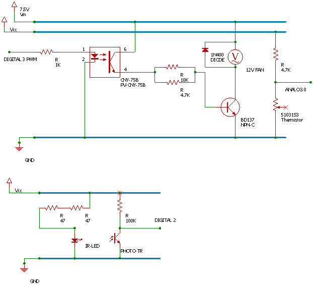
The temperature sensor U2 needs to be located next to the item being monitored. As the temperature increases the motor duty cycle will increase. D1 and R2 are optical components, they only need to be installed for a visual...
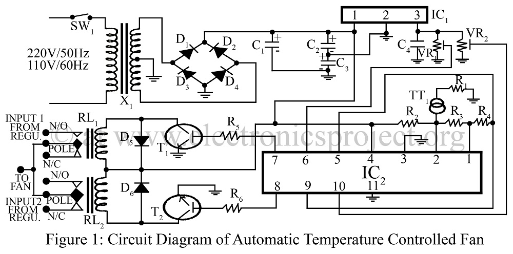
An automatic temperature-controlled fan regulates the fan speed based on temperature variations using the temperature transducer AD590 and an op-amp LM324 circuit diagram. The automatic temperature-controlled fan circuit utilizes the AD590 temperature transducer, which provides an output voltage that is...
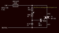
The circuit operates by adjusting the firing angle of the Triac. Resistors R1, R2, and capacitor C2 are involved in this process. The firing angle can be modified by changing the value of any of these components, with R1...
The controller circuit is designed to reduce a fan's noise, power consumption, and wear, especially when operating in low, fluctuating ambient temperatures. A temperature sensor is mounted in the fan's airstream, allowing the circuit to adjust the fan speed...
This report presents a comprehensive overview of a mini project titled "Remote Controlled Fan Regulator," developed in accordance with the curriculum requirements for the sixth semester of the Bachelor of Technology degree in Electrical and Electronics Engineering. The report...