IR (Infrared) Detector Circuit
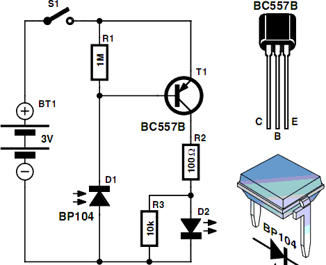
Men particularly enjoy the convenience of television remote controls, often to the annoyance of their female partners. They tend to want to know what they are missing when the TV is tuned to a specific program, leading them to frequently switch channels. With the remote control in hand, they feel in control of the TV set. However, they are at a loss when the remote control malfunctions. Various factors can cause a remote control to fail, including a defective infrared (IR) receiver in the TV, issues within the remote control itself, or depleted batteries. A tester that can determine whether the remote control is still emitting an IR signal can be quite useful. For those who wish to maintain control over their IR devices, constructing a personal IR detector can be beneficial.
An infrared (IR) detector circuit can be designed to ascertain whether a remote control is functioning correctly by detecting the IR signals it emits. The essential components of this circuit include a photodiode or phototransistor sensitive to IR light, a resistor, and a simple microcontroller or an LED indicator to provide visual feedback.
The circuit operates by positioning the photodiode or phototransistor to receive IR light from the remote control. When the remote is activated, it emits a modulated IR signal, which the photodiode converts into a small electrical current. This current is then amplified by a transistor or processed by a microcontroller, which can be programmed to recognize the specific modulation frequency of the IR signal.
To power the circuit, a battery or a power supply can be used. A resistor is typically placed in series with the photodiode to limit the current and protect the component from potential damage. The output can be visualized using an LED that lights up when an IR signal is detected, or it can be fed into a microcontroller for more advanced processing, such as displaying the signal strength or logging the detection events.
This simple IR detector circuit can be constructed on a breadboard for testing and can be miniaturized into a compact housing for practical use. By building this IR detector, users can effectively troubleshoot remote control issues, ensuring that they maintain control over their television viewing experience.Men in particular enjoy the convenience of television remote controls often to the annoyance of their female partners. Men apparently want to know what they re missing when the TV is tuned to a particular program, so they like to keep zapping to other channels.
With the remote control in their hands, they feel like they are the lord and master of the TV set. They are thus completely at a loss if the remote control doesn t work properly. There are many reasons why a remote control unit can malfunction, such as defective IR receiver in the TV set, a defect in the remote control, or empty batteries. Here a tester that can determine whether the remote control unit still emits an IR signal can come in handy.
If you want to keep the IR reins ?rmly in hand, you can build your own IR detector.. 🔗 External reference

