
IR (infrared) receiver and transmitter
 receiver and transmitter")
The project involves the integration of infrared (IR) LEDs with an IR phototransistor to create a simple optical communication system or a basic IR sensor circuit. The IR LED emits infrared light, which is typically invisible to the human eye, while the phototransistor detects this emitted light, allowing for the conversion of light signals into electrical signals.
In this circuit, the IR LED is connected in series with a current-limiting resistor to ensure it operates within its specified current range. The anode of the IR LED is connected to the positive terminal of a power supply, while the cathode is connected to one end of the resistor. The other end of the resistor is grounded. This configuration allows the LED to emit infrared light when powered.
The IR phototransistor is connected to a different part of the circuit. Its collector is connected to a positive voltage supply, while the emitter is connected to ground through a load resistor. When the IR LED is activated, it emits infrared light that can be detected by the phototransistor. The phototransistor will conduct when it receives sufficient IR light, allowing current to flow from the collector to the emitter, which can be used to trigger further actions in the circuit, such as activating a relay or lighting an indicator LED.
To enhance the performance of the circuit, it is advisable to use a suitable resistor value for both the IR LED and the phototransistor, depending on their specifications. Additionally, the distance between the IR LED and the phototransistor should be optimized to ensure reliable operation, as the intensity of the emitted infrared light decreases with distance.
This basic circuit can serve as a foundation for various applications, such as remote control systems, simple obstacle detection, or proximity sensors, demonstrating the versatility of IR components in electronic projects.Hello all, Recently I acquired some samples of IR LED`s, and a matching IR Phototransistor. I was bored, and decided to make something with it!.. 🔗 External reference
Related Circuits
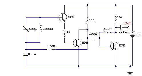
This wireless headphone transmitter ensures a reliable connection over a distance of 2 meters. The oscillator frequency ranges between 1750 KHz and 3500 KHz, utilizing a ferrite bar as the antenna. IC1 amplifies the audio signal, while TC1 serves...
This circuit represents a conventional Colpitts type crystal oscillator, where the output is taken from a low-value collector load resistor. Direct coupling is implemented into the base of a PNP transistor used as an amplifier, resulting in a simplified...

This Stereo FM Transmitter with BA1404 enables the creation of a mini stereo FM station, allowing for wireless audio broadcasting throughout a home. It provides a straightforward method for establishing an audio link without the need for complex wiring....
This is a compact three-transistor regenerative receiver with fixed feedback. It is similar in principle to the ZN414 radio IC, which is no longer available. The design is simple, and the sensitivity and selectivity of the receiver are good....
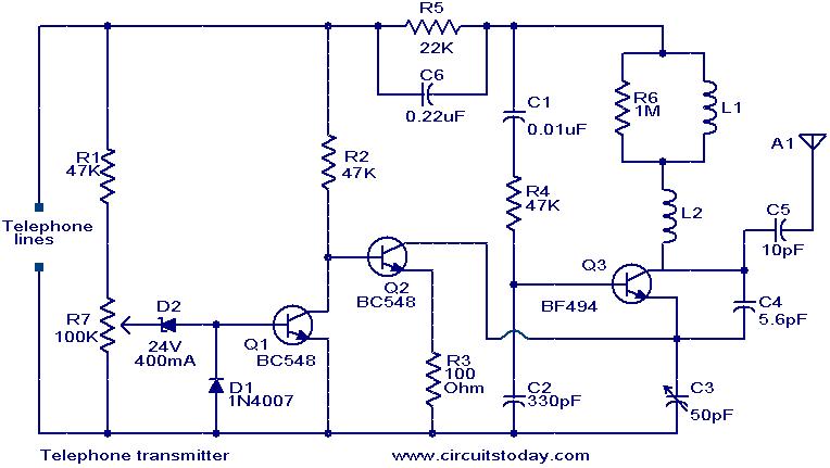
This circuit is a simple yet effective design for transmitting telephone conversations. When the telephone receiver is on-hook, the voltage across the lines is approximately 48 volts. The preset resistor R7 is adjusted to achieve a voltage of 24.7...
The RF oscillator employs inverter N2 and a 10.7 MHz ceramic filter to drive the parallel configuration of inverters N4 to N6 via N3. Due to the parallel arrangement of these inverters, the output impedance is low, allowing for...