
wireless headphones transmitter

The wireless headphone transmitter circuit design is centered around achieving optimal audio transmission within a short range, specifically up to 2 meters. The oscillator frequency, adjustable between 1750 KHz and 3500 KHz, is crucial for maintaining a stable and clear audio signal. The choice of a ferrite bar antenna enhances the efficiency of the transmission by providing a compact and effective radiating element.
The integration of IC1 as an audio signal amplifier ensures that the sound quality is preserved and amplified before transmission. This component is essential for driving the audio signal to sufficient levels, allowing for clear sound reproduction in the headphones. TC1 functions as a buffer, isolating the amplifier from the oscillator circuit, which helps in maintaining signal integrity and reducing distortion.
D1, a vital component in the circuit, serves dual purposes: it indicates the operational status of the transmitter and stabilizes the voltage supplied to the oscillator. This stabilization is necessary to prevent fluctuations that could affect the oscillator's performance and, consequently, the audio quality.
The inductor L1, designated as a toroidal inductor T50-2, is constructed with 80 turns of 0.2 mm gauge wire. This design choice is significant as it contributes to the inductance required for optimal oscillator performance. The inductance value influences the frequency characteristics of the transmitter, ensuring it operates effectively within the specified range.
In terms of the antenna structure, L2 requires a ferrite bar of 10-20 cm in length, which is critical for achieving the desired range and transmission quality. L2a, with its 3 turns of 0.6 mm gauge wire, is wound at one end of L2b, which consists of 30 turns of 0.5 mm gauge wire. This configuration is designed to enhance the magnetic field produced by the antenna, improving the overall transmission efficiency and range of the wireless headphone system. The careful selection of wire gauge and the number of turns in the inductors are key factors that influence the performance characteristics of the circuit, ensuring reliable audio transmission for the user.This wireless headphones transmitter assures a affection accession over 2 meters. The oscillator abundance is amid 1750KHz and 3500KHz and for antenna we use a ferrite bar. IC1 amplifies the audio arresting and TC1 is a buffer. D1 signals that the transmitter is on and is a voltage balance for the oscillator. L1 is a toroidal amount T50-2 with 80 turns, 0. 2mm G. L2 requires a 10-20cm ferrite bar, L2a has 3 turns, 0. 6mm G coiled at arena end of L2b wich has 30 turns, 0. 5mm G. 🔗 External reference
Related Circuits
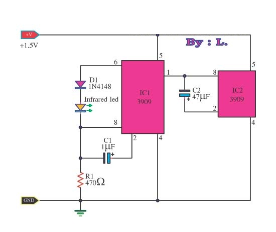
This circuit is an infrared transmitter that operates on a low power supply of 1.5 V. The main components include two LM3909 integrated circuits, which function as an oscillator and LED flasher. Typically, this circuit is utilized as a...
An infrared (IR) transmitter-receiver system is being developed to send signals to a device, specifically a simple blue LED. The proposed infrared transmitter-receiver system consists of two main components: the IR transmitter and the IR receiver. The transmitter will emit...
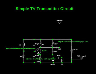
Many individuals inquire about TV transmitters. This document provides a useful circuit diagram that enables signal transmission over distances of 75 to 100 meters. The circuit diagram is not original but was provided by a colleague. Contributions of circuit...
3-3.5 Watt FM Transmitter. This is the schematic for an FM transmitter with 3 to 3.5 W output power that can be used between 90 and 110 MHz. Although the stability is not so bad, a. The 3-3.5 Watt FM...
This circuit utilizes a sawtooth oscillator along with an output amplifier that drives a transistor. The components C1, C2, and L1 are essential for the oscillator's operation, forming a tank circuit that must be tuned to the resonant frequency....
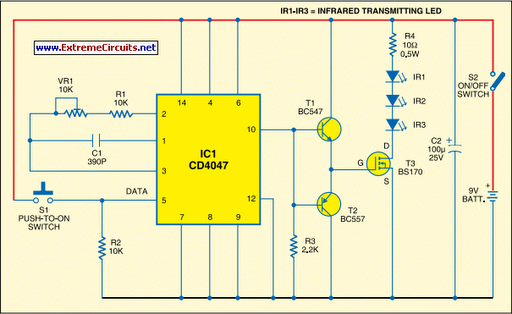
Most IR remotes operate reliably within a range of 5 meters. Designing an IR transmitter for reliable operation over a longer range, such as 10 meters, increases circuit complexity. To double the range from 5 meters to 10 meters,...