
IR Interval Timer for Pentax DSLR Camera

The IR interval timer circuit is designed to automate the process of taking photographs at specified intervals, making it ideal for capturing gradual changes in the environment, such as the transition from day to night. The core components of this circuit typically include a microcontroller, an infrared emitter and receiver, a relay or transistor for controlling the camera shutter, and a power supply.
The microcontroller serves as the brain of the timer, programmed to execute a series of commands that dictate the timing of the image capture. It can be programmed with various intervals, allowing the user to select how frequently the images are taken. The infrared emitter sends a signal to the receiver, which detects the presence of an object or person in front of the camera, ensuring that the timer only activates when needed.
A relay or transistor is used to interface with the camera's shutter mechanism. This component allows the circuit to control the shutter without requiring a direct connection to the camera, preserving the integrity of the camera's electronics. The power supply must be robust enough to support the entire circuit, ensuring stable operation during extended shooting sessions.
Additional features may include an LCD display for user feedback, allowing for easy adjustments to the timer settings, and buttons for user input. The design can also incorporate a battery backup system to ensure functionality in outdoor environments where power sources are not readily available.
Overall, the IR interval timer project combines various electronic components to create a versatile tool for photographers and videographers, enabling the capture of stunning time-lapse sequences with minimal manual intervention.This project aims to build an IR interval timer which can be used to capture images such as time lapse movies of sunrise or sunrise and the night sky. The.. 🔗 External reference
Related Circuits
Telephones are declining globally; however, India has over 350 million mobile phone users, alongside a significant number of traditional telephone users. This telephone timer is designed to save costs by controlling unnecessary time spent during phone calls. This simple...
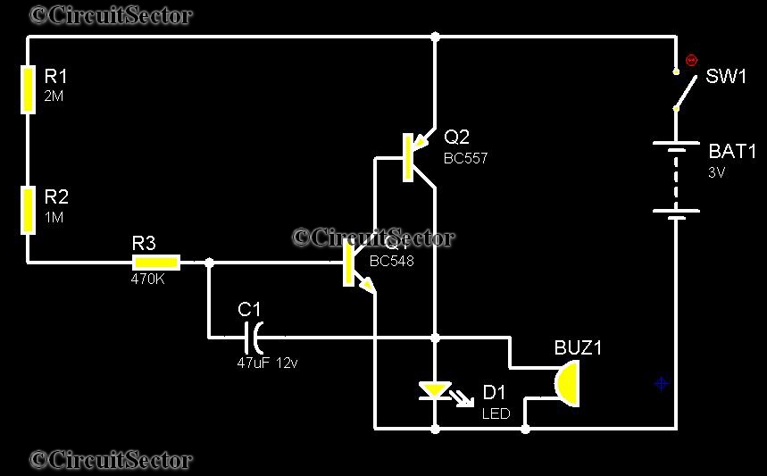
This timer was designed primarily to switch off a portable radio after a set period. This feature allows users to fall asleep on the beach or in a hammock, knowing that the receiver will automatically turn off after a...
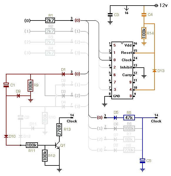
This circuit utilizes a CMOS 4017 decade counter, which begins counting from zero and increments by one each time pin 14 is activated. Upon reaching a count of nine, it resets to zero and starts the counting process again....

A project is underway that necessitates the conversion of a 0-10V DC supply into a linear frequency range in the form of a square wave. The project involves designing a circuit that takes a direct current (DC) voltage input ranging...
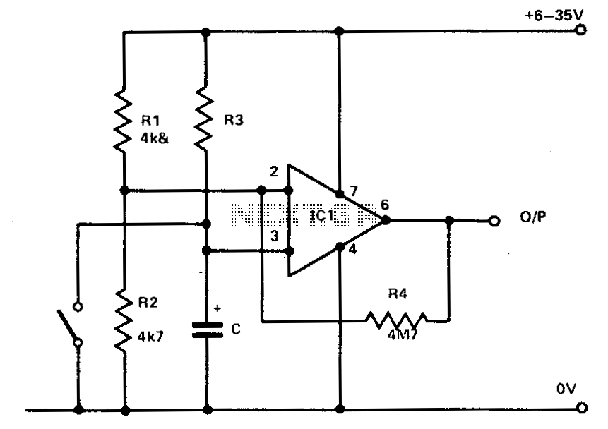
R1 and R2 maintain the inverting input at half the supply voltage. R4 provides feedback to enhance the input impedance at pin 3. Pin 3, which is the non-inverting input, is connected to the junction of R3 and C....
The water sensor circuit utilizes a 555 timer circuit along with common electronic components. It consists of two metal electrodes positioned closely enough that a drop of water can create a conductive bridge between them. If the water is...