
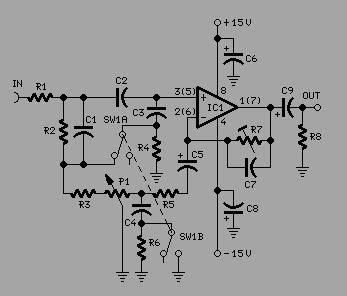
ir remote circuit

The infrared remote control circuit operates by using an infrared LED to emit a modulated signal, which is typically a square wave tone. The modulation frequency can vary, but common frequencies are in the range of 30 kHz to 40 kHz. This modulation allows the receiver to differentiate between the remote control signal and other ambient infrared signals, such as sunlight or incandescent lighting.
The schematic for the infrared remote control consists of several key components:
1. **Infrared LED**: This component emits the infrared light signal when activated. It is driven by a transistor or a microcontroller output pin, which modulates the LED based on the desired tone.
2. **Modulation Circuit**: A simple oscillator circuit can be used to generate the modulation frequency that drives the infrared LED. This can be implemented using a 555 timer IC configured in astable mode or a microcontroller programmed to output a PWM signal.
3. **Power Supply**: The remote control circuit typically requires a low-voltage power supply, often provided by batteries. A voltage regulator may be included to ensure stable operation.
4. **Control Buttons**: The remote will include push buttons that, when pressed, send specific commands. These buttons are connected to the modulation circuit to trigger the appropriate tone corresponding to each command.
5. **Receiver Circuit**: The receiving end consists of an infrared photodiode or phototransistor that detects the incoming infrared signal. This component is often paired with a bandpass filter to isolate the modulation frequency, enhancing the receiver's ability to recognize the intended signal.
6. **Decoding Circuit**: Once the signal is detected, it is processed by a microcontroller or other logic circuitry that decodes the tone. Based on the decoded signal, the receiver can then control other devices, such as turning on a light or activating a motor.
7. **Output Control**: The decoded signals can be used to drive relays or transistors to control higher power devices, ensuring that the remote can operate a variety of electronic appliances.
This design allows for a reliable and user-friendly interface, where the user can control devices without the risk of accidental activation, as the receiver will only respond to the specific tone generated by the remote. The simplicity of the circuit design also makes it suitable for various applications, from home automation to remote-controlled toys.I have received a number of emails requesting schematics for infa-red remotes. So here is one. This remote transmits a tone using an infa-red LED. This tone is decoded by the receiver. Since the receiver only switches when it "hears" the tone, there are no accidental activations. 🔗 External reference
Related Circuits
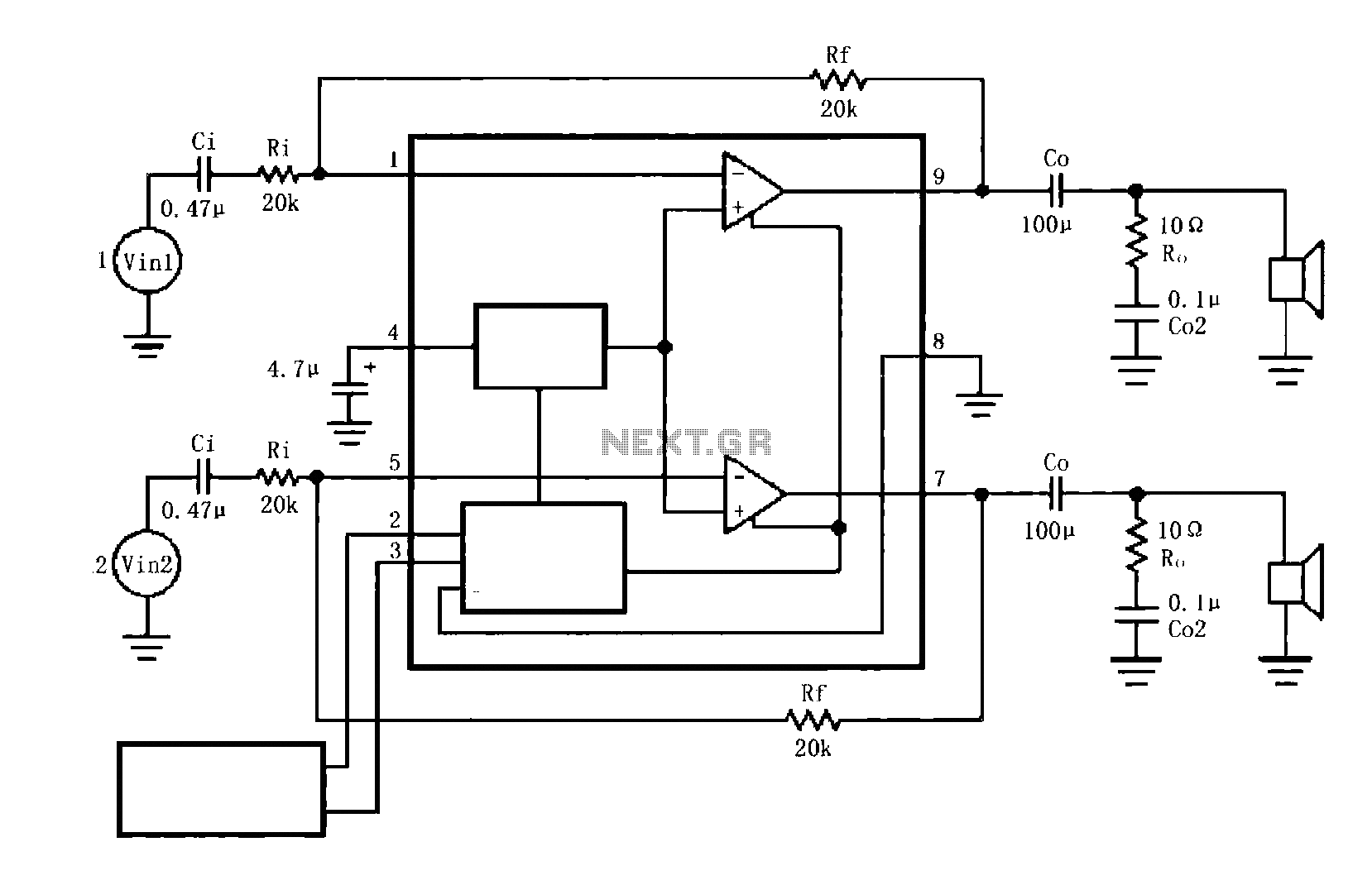
The circuit illustrated is a typical configuration for the LM4916 two-channel amplifier. The left and right channel audio signals are fed into the LM4916, which amplifies them internally. The output is then delivered through a coupling capacitor (Co) to...
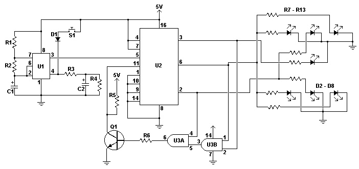
An electronic dice is a classic introductory project for individuals interested in electronics. It consists of a timer, counter, and several LEDs, forming a circuit that adds an engaging element to traditional board games. When the switch is activated,...
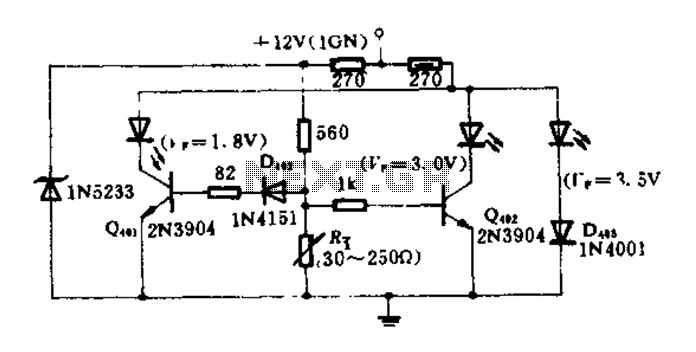
The circuit diagram illustrates how an oil pressure sensor is transformed into a variable resistor, denoted as Rt. Variations in Rt lead to changes in the biasing of each transistor, which in turn controls three LEDs (red, yellow, and...
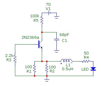
This article presents basic circuits for pulsing infrared LEDs and low-power visible semiconductor lasers utilizing inexpensive and readily available components. Numerous interesting and practical applications are referenced, alongside several online resources. The focus of the article is on the...
To achieve optimal audio reproduction at various listening levels, it is essential to incorporate tone-setting controls that align with the well-documented characteristics of human auditory perception. Specifically, human ear sensitivity exhibits a non-linear response across the audible frequency spectrum,...
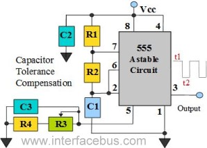
The 555 Timer is configured as an astable multivibrator. Additional components have been incorporated to enhance circuit operation. Upon powering the circuit, the 555 Timer will generate a square wave, determined by the values of Capacitor C1 and Resistors...