
ir remote control home appliances

The proposed infrared remote control circuit is a versatile solution for home automation, leveraging the capabilities of the CD4017 decade counter to manage multiple outputs based on the received IR signals. The TSOP1738 infrared receiver is specifically selected for its sensitivity to the 38KHz carrier frequency, which is standard for consumer remote controls, ensuring compatibility with a wide range of devices.
The inclusion of the 555 Timer configured as an astable multivibrator provides a reliable clock signal that drives the CD4017. The timer's frequency can be adjusted to optimize the response time of the circuit, allowing for quick and efficient control of home appliances. The use of transistors for signal amplification ensures that the output from the TSOP1738 can effectively drive the clock input of the CD4017, maintaining signal integrity and responsiveness.
The circuit's design also incorporates visual indicators through the use of LEDs, which provide immediate feedback regarding the status of the appliances being controlled. This feature enhances user interaction and allows for easy monitoring of the system's operation. The relay interface is crucial for controlling high-power devices, ensuring that the low-power signals from the logic components can safely operate larger loads.
Overall, this IR remote control circuit exemplifies a practical application of basic electronic components to create an effective home automation solution, enabling convenient control of various appliances from a distance. The design can be further enhanced by integrating additional features such as programmable settings or multiple device control, depending on user requirements.An IR Remote Control for controlling home appliances can be easily made using Decade Counter CD4017, 555 Timer and TSOP1738 infrared receiver. By using this circuit you can easily control your home appliances using your TV, DVD Player remote control or using a remote control circuit described here.
2nd and 1st pins of TSOP1738 are used to give power, Vcc and Gnd respectively. 100G © resistor and 33G F capacitor is to suppress power supply disturbances. When IR rays at 38KHz falls on TSOP1738, output (3ed pin) goes low, since the output is active low. This output is amplified by the transistor Q1 and is given to the clock input of CD4017. 16th and 8th pins of CD4017 is used to give power Vcc and Gnd respectively. Enable (13th pin) is tied to Gnd to enable the IC, since it is an active low input. Output Q2 (4th pin) is connected to Reset MR (15th pin) to make CD4017 a bistable multivibrator. During the first clock signal Q0 becomes high, second clock signal makes Q1 high (Q0 becomes low) and the third clock signal makes Q0 high (since Q2 is connected to MR, third clock signal resets the counter). Lets assume the counter is Reset state (Q0 high and others low). When the remote is pressed, clock signal is generated which makes Q1 is high. Thus LED D1 glows, transistor Q2 turns ON and which energizes the relay. When the remote is pressed again, Q0 becomes high LED D2 glows. LED D1 indicates when the appliance is ON and LED D2 indicates when the appliance is OFF. TSOP1738 detects only those signals whose carrier frequency is around 38KHz. Thus it is accomplished using Astable Multivibrator using 555 timer. Please read this article for more details about above circuit. 🔗 External reference
Related Circuits
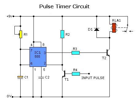
Today, solutions are offered for a timed control relay that utilizes Normally Open (NO) and Normally Closed (NC) contacts to manage the operation of other devices, enabling or disabling them as needed. The functionality of this circuit is based...
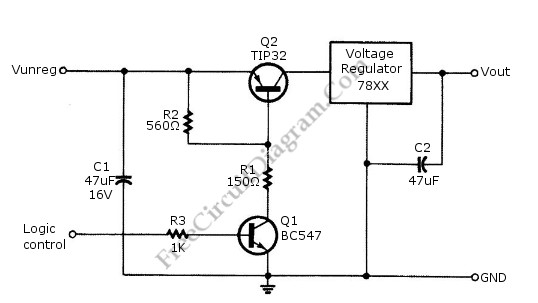
Logic power control of an analog regulator can be useful in applications where a digital circuit or controller needs to manage a power source, such as in EEPROM programmers or other power control systems. This circuit provides ON-OFF control...
The AVR 8-Bit RISC microcontroller from Atmel is a widely used microcontroller. This microcontroller integrates EEPROM, RAM, an Analog to Digital converter, numerous digital input and output lines, timers, UART for RS-232 communication, and various other features. An article...
The motor winding is configured with delta transposition capacitance, designated as cl-C-3G. It operates as a DC LAN speed generator and is associated with a three-phase asynchronous motor, which is coaxially connected through a field winding powered by a...
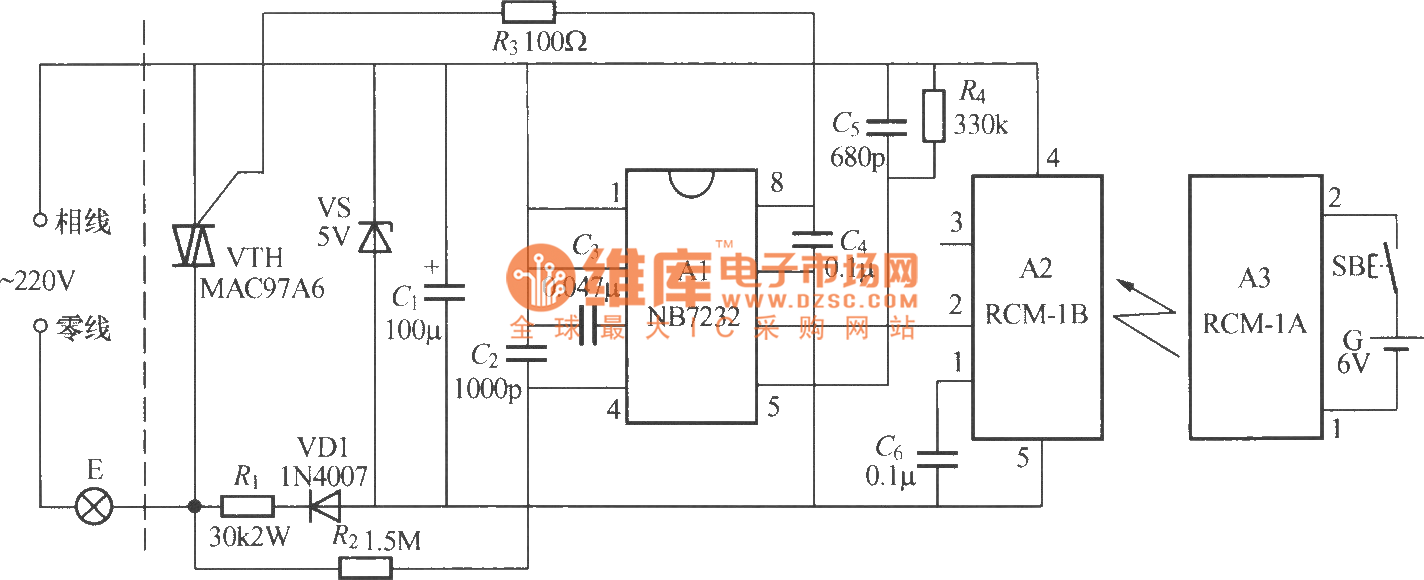
The diagram above illustrates a radio remote control dimmer circuit. This circuit utilizes a micro radio transmit/receive module in conjunction with a light modulation ASIC, resulting in a compact and easily producible design. It operates reliably and features a...
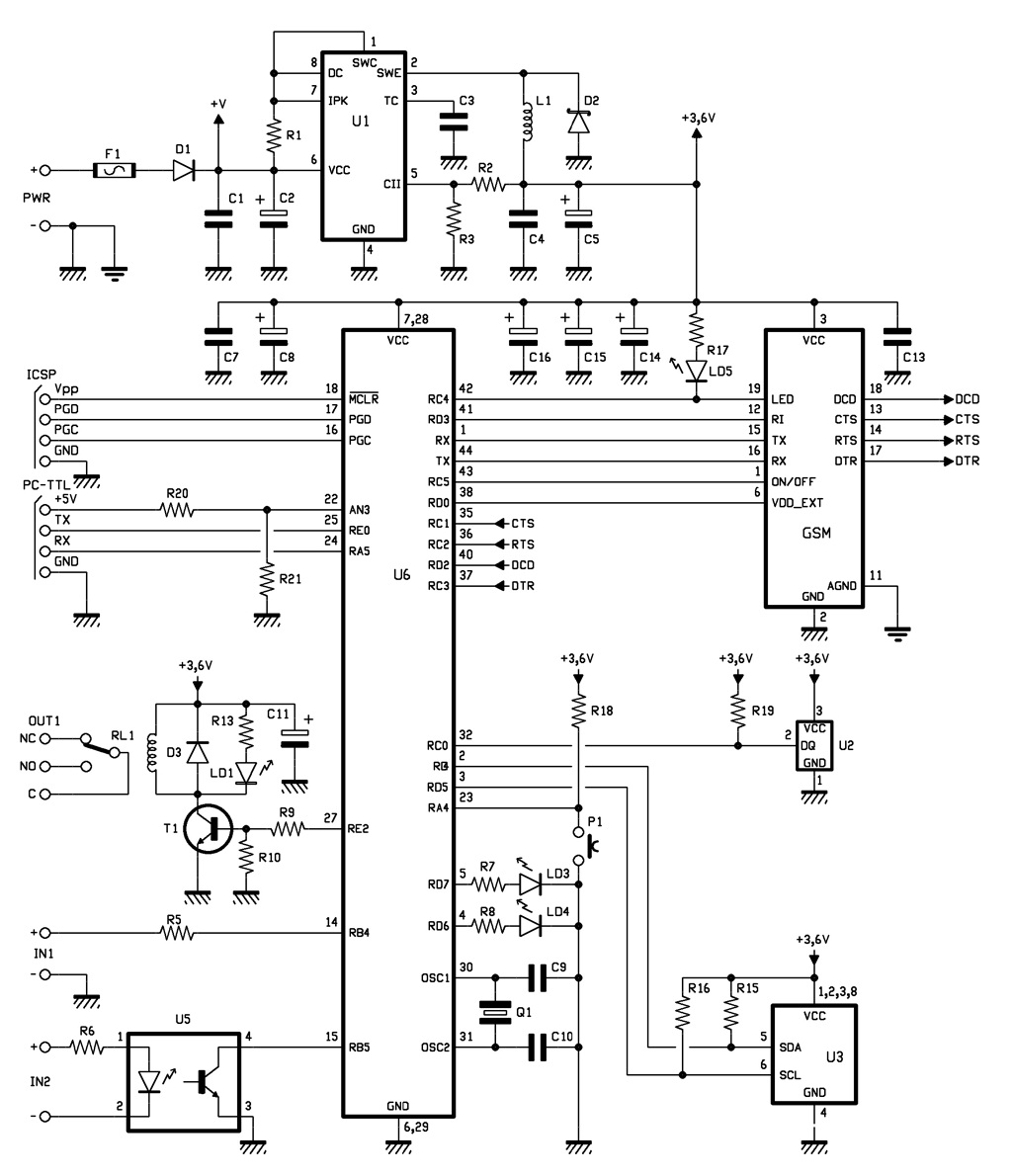
The complete GSM thermostat is controlled by a Microchip PIC18F46K20-I/PT microcontroller, which is programmed with firmware to manage temperature regulation and facilitate communication with the GSM module. This module, referred to as GSM, is a compact board that contains...