
Ir Remote Extender

This infrared signal repeater circuit is designed to facilitate the remote operation of audio and video playback devices from a distance, enhancing user convenience in multi-room setups. The circuit primarily consists of an infrared LED (LED2) for transmitting the signal and a visible light LED (LED1) that serves as an indicator for successful transmission.
The infrared LED is responsible for emitting the infrared light that corresponds to the commands received from the remote control. The signal is initially captured by a sensor that detects the infrared signal emitted by the remote. This signal is then converted into a suitable form and transmitted through connecting wires to the infrared LED, which re-emits the signal towards the VCR or CD player.
The inclusion of the 100-KOhm trimmer potentiometer (R1) allows for fine-tuning of the circuit's sensitivity, enabling the user to adjust how effectively the circuit responds to the remote control's signals. This adjustment is crucial in environments where interference may affect signal reception, ensuring reliable operation regardless of the distance or obstacles between the remote and the receiving device.
The omission of a resistor in series with the LEDs is a notable design feature, as the voltage drop across the connecting lines typically results in a sufficient voltage level (approximately 1.0 Vdc) for the LEDs to function correctly. This design choice simplifies the circuit and reduces component count while maintaining effective operation.
Overall, this infrared signal repeater circuit is an efficient solution for extending the range of infrared remote controls, making it suitable for various applications in home entertainment systems. This circuit can be used to operate a VCR or CD player from another room. It"s really an infrared signal repeater. The s ignal from the remote is received and then retransmitted over wires to an infrared LED. The beam from the LED is then picked up by the receiving window on the VCR or CD player. The visible light LED (LED1) in series with the IR unit (LED2) is used to indicate that the transmitted signal has been detected. The 100-KOhmhm trimmer potentiometer (RI) adjusts the repeater"s sensitivity. The resistor that is usually found in series with the LEDs is omitted, because the voltage reading is about 1.0 Vdc as a result of the voltage drop across the lines.
Related Circuits
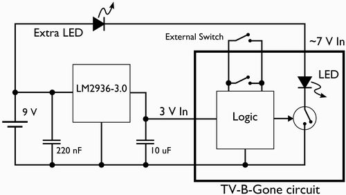
This document outlines the process of modifying a TV-B-Gone device to fit into the casing of a vintage television remote control. The original on/off button of the remote will be repurposed to activate the TV-B-Gone. Additionally, the power supply...
This is an enhanced infrared (IR) remote control extender circuit. It features high noise immunity, resistance to ambient and reflected light, and an extended range of approximately 7 meters from the remote control to the extender circuit. It is...
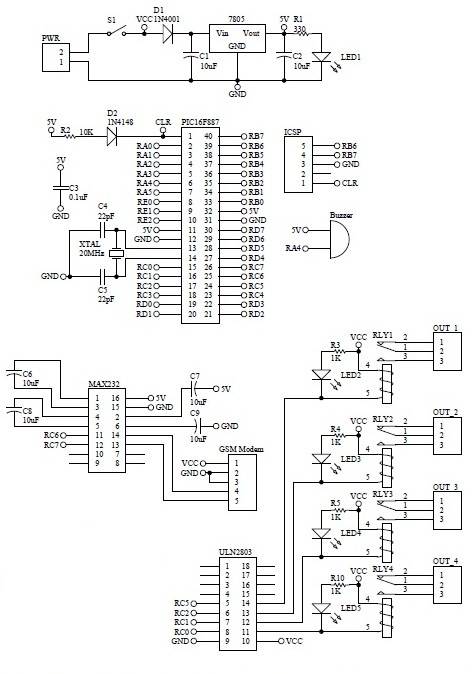
How to turn on equipment by sending SMS `1111` to switch it ON and switch off the equipment by sending SMS `0000`. The GSM switch will receive instructions for either load 1 (L1), load 2 (L2), load 3 (L3),...
It is easy to miss the sound of a doorbell while watching TV. This circuit addresses the issue by providing a visual indication, such as a lamp or an LED. Connecting a lamp directly in parallel with the doorbell...
This circuit is designed to disrupt infrared (IR) remote signals, allowing users to override volume settings on a stereo, change TV channels, or create general interference. Key components include a ceramic capacitor, an electrolytic capacitor, a resistor, a battery,...
While developing an infrared (IR) extender circuit, a method was required to measure the relative intensities of different infrared light sources. This circuit is the culmination of that research. It utilizes a photodiode, specifically the SFH2030, as the infrared...