
ir remote control tester

The infrared extender circuit is designed to effectively measure and compare the intensity of various infrared light sources, notably remote control units. The core components of the circuit include the SFH2030 photodiode, which is sensitive to infrared light, and the CA3140 operational amplifier configured in a differential mode. This configuration allows for precise amplification of the small current generated by the photodiode when exposed to infrared radiation.
The circuit operates by converting the detected infrared light into an electrical signal. When infrared light strikes the photodiode, it generates a current proportional to the intensity of the light. This current is then amplified by the CA3140 operational amplifier, which is essential for achieving a measurable output voltage. The output voltage at pin 6 of the op-amp can be directly correlated to the intensity of the incoming infrared light, making it possible to quantify the strength of various remote control signals.
The inclusion of LED1 serves as a visual indicator of infrared light detection. It provides immediate feedback to the user, signaling that the photodiode is receiving IR radiation. This feature enhances the usability of the circuit during testing and adjustments.
The output voltage can be monitored using a multimeter set to measure DC voltage, allowing for a straightforward comparison of the strength of different infrared remote controls. The circuit is designed to work effectively at a distance of approximately one meter, which is a common range for infrared remote controls. The relationship between the current through the photodiode and the output voltage is linear, with every microamp of current resulting in about one volt at the output.
It is important to note that not all operational amplifiers are suitable for this application. The CA3140 is preferred due to its characteristics, while common alternatives like the 741 or LF351 do not provide the necessary performance for this circuit. Additionally, the circuit can be powered by either a 12-volt power supply or a 9-volt battery, offering flexibility in power sourcing depending on the application requirements.
Overall, this infrared intensity measurement circuit presents a reliable solution for evaluating the performance of infrared light sources, particularly in the context of remote control devices.As I was developing my IR Extender Circuit, I needed to find a way of measuring the relative intensities of different Infra red light sources. This circuit is the result of my research. I have used a photodiode, SFH2030 as an infra red sensor. A MOSFET opamp, CA3140 is used in the differential mode to amplify the pulses of current from the photodi
ode. LED1 is an ordinary coloured led which will light when IR radiation is being received. The output of the opamp, pin 6 may be connected to a multimeter set to read DC volts. Infra red remote control strengths can be compared by the meter reading, the higher the reading, the stronger the infra red light. I aimed different remote control at the sensor from about 1 meter away when comparing results. For every microamp of current through the photodiode, about 1 volt is produced at the output. A 741 or LF351 will not work in this circuit. Although I have used a 12 volt power supply, a 9 volt battery will also work here. 🔗 External reference
Related Circuits
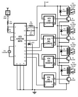
This project utilizes DTMF (dual-tone multi-frequency) signals, commonly used in telephones for dialing digits, as control codes. The DTMF tones are employed for frequency modulation of the carrier signal. At the receiver unit, these frequency-modulated signals are intercepted to...
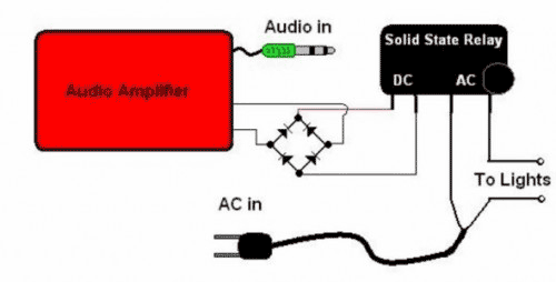
The basic Idea was to have Christmas lights flash with the music. In my design I use an ordinary amplified computer speaker, a diode bridge, and a ‘CRYDOM’ SSR (Solid State Relay). In order to increase the time that...
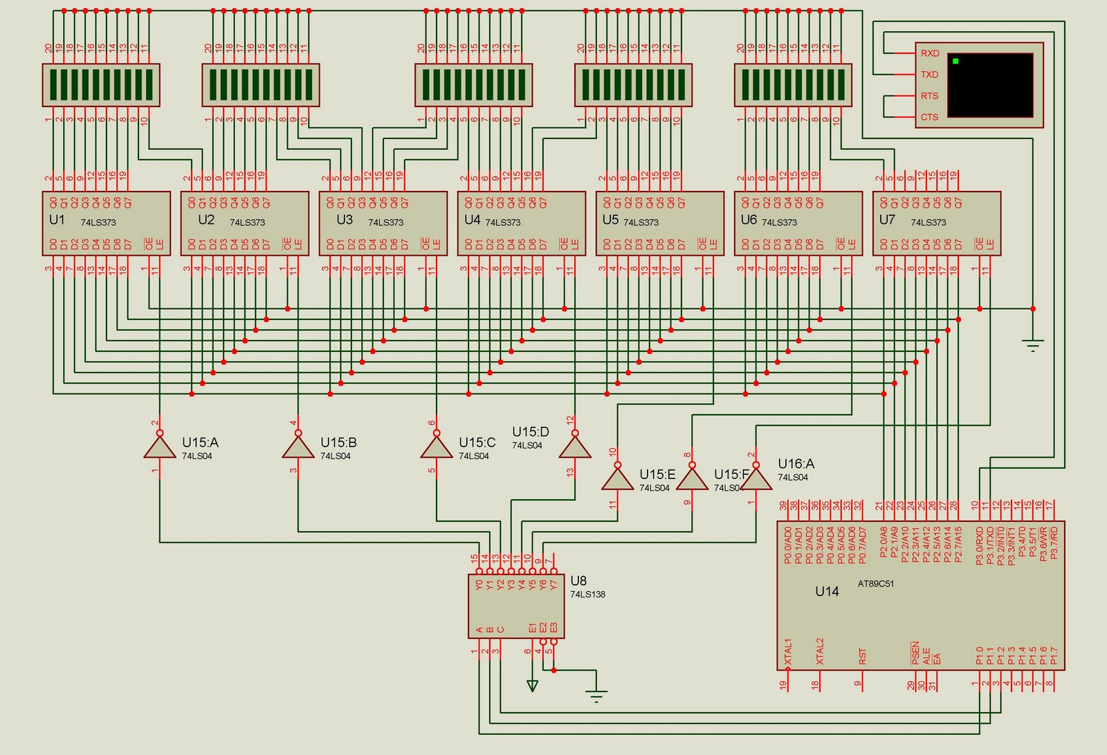
This project is designed to control up to 50 solid-state relays independently. It serves as an excellent learning resource for students who wish to expand the input-output lines of a microcontroller and control multiple devices. The ON or OFF...
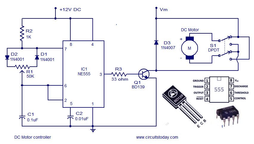
A DC motor controller based on an NE555 timer is presented here. The direction of rotation of the DC motor can also be changed using this DC motor speed control circuit. The described circuit utilizes the NE555 timer IC in...
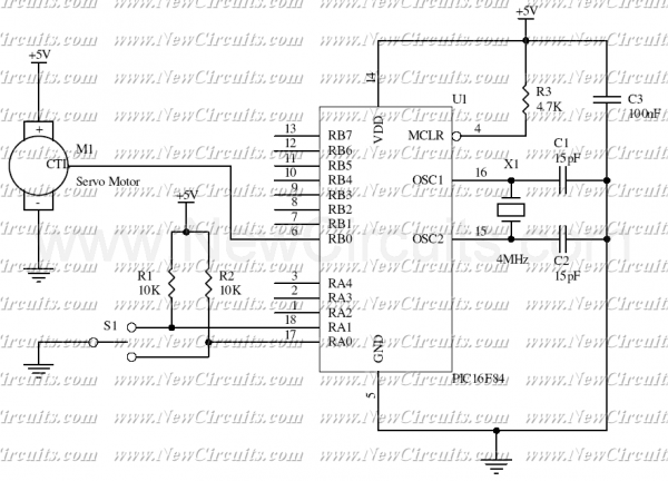
This simple micro-control circuit controls a servo motor according to a 3-state switch. A servo motor acts as an actuator in 3 positions. It has 3 wires, one for VCC, one for Ground, and another one for position control....
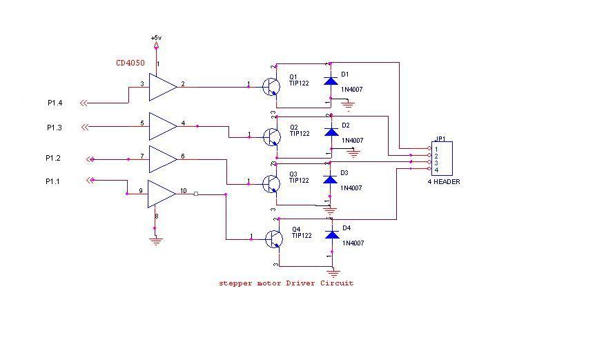
A 6V, 2A stepper motor is utilized in this circuit. The CD4050 hex buffer is employed to connect to the microcontroller. The output of the CD4050 is linked to the base of a TIP122 transistor. The emitter and collector...