
IR S/PDIF Receiver

This circuit is designed to work in conjunction with the IRS/PDIF transmitter, forming a robust system for infrared communication. The IRS/PDIF transmitter converts digital audio signals into infrared light signals, which can be transmitted wirelessly. The IR receiver, on the other hand, captures these infrared signals and converts them back into audio signals for playback through speakers or other audio devices.
The circuit typically includes several key components: a photodiode or phototransistor as the IR receiver, an amplifier circuit to boost the received signal, and a decoder to interpret the signal and convert it into an audio format. The photodiode is positioned to receive the infrared signals emitted by the transmitter. When the infrared light hits the photodiode, it generates a small current that is proportional to the intensity of the light.
The amplifier circuit is crucial as it increases this small current to a level suitable for processing by the decoder. Operational amplifiers (op-amps) are commonly used in this stage to ensure that the signal is clean and strong enough for further processing. The output of the amplifier feeds into a decoder circuit, which may be a microcontroller or a dedicated audio decoder IC. This component interprets the digital signal and converts it into an analog audio signal.
The overall design of the circuit should also consider power supply requirements, ensuring that both the transmitter and receiver operate efficiently without interference. Additionally, careful layout and shielding may be required to minimize noise and ensure reliable communication between the transmitter and receiver.
In summary, this circuit provides an effective means of transmitting audio signals wirelessly through infrared light, utilizing a combination of photodetection, amplification, and signal decoding to achieve high-quality audio reproduction.This simple circuit proves to achieve surprisingly good results when used with the IRS/PDIF transmitter described elsewhere in this site. The IR receiver.. 🔗 External reference
Related Circuits
Most telephone equipment today utilizes a DTMF receiver integrated circuit (IC). A widely used DTMF receiver IC is the Motorola MT8870, which consists of 18 pins and is employed in telephones and various other applications. When projects utilizing this...
This receiver operates within the frequency range of 8.5 to 11.5 MHz across two distinct bands and exhibits a sensitivity level of less than 1 µV. The NE602 mixer is utilized to feed a 455 kHz intermediate frequency (IF)...
The performance of this sensitive ultrasonic receiver is impressive. It allows users to listen to various sources of ultrasonic sounds, including bugs, bats, and engines. The circuit utilizes a piezo tweeter as an ultrasonic microphone, with amplifier stages Q1...
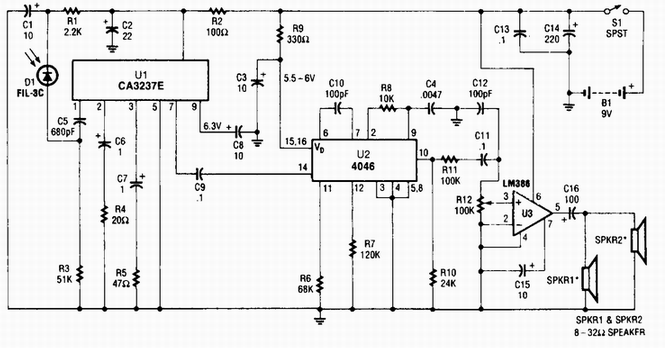
A photodiode D1 feeds a high-gain infrared (IR) remote control preamplifier IC, specifically a CA3237E. U2 is a phase-locked loop (PLL) frequency modulation (FM) detector tuned to approximately 100 kHz. The output from the detector is amplified by U3,...

This circuit is an FM radio receiver that is very small in size and operates effectively, although its sensitivity is limited. The principle of this circuit is based on the use of a generator. The FM radio receiver circuit typically consists...
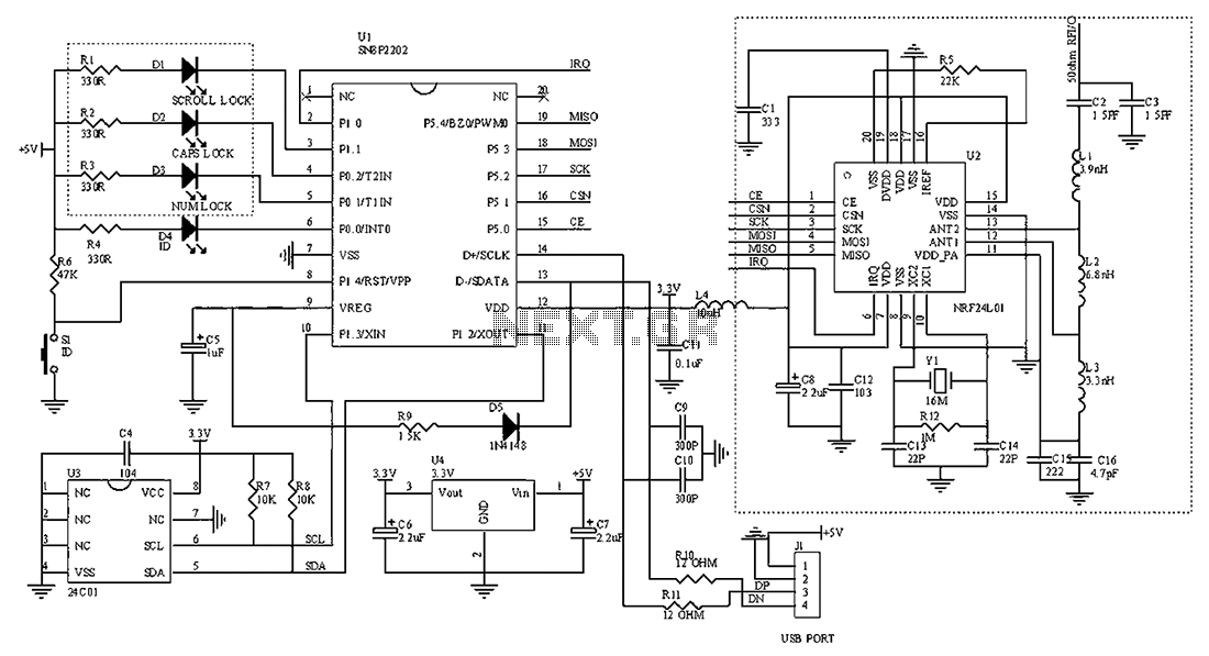
The circuit diagram for the receiving portion of a 2.4 GHz wireless keyboard is presented below. The 2.4 GHz wireless keyboard receiving circuit typically consists of several key components that work together to receive and process signals transmitted from the...