
Small FM radio receiver

The FM radio receiver circuit typically consists of several key components, including an antenna, RF amplifier, mixer, local oscillator, demodulator, and audio amplifier. The antenna captures radio frequency signals, which are then amplified by the RF amplifier to improve signal strength. The mixer combines the amplified RF signal with a signal from the local oscillator to produce an intermediate frequency (IF) signal. This IF signal is then demodulated to extract the audio information, which is subsequently amplified by the audio amplifier for output to speakers or headphones.
In a compact design, the circuit may utilize integrated circuits (ICs) to minimize size and enhance performance. The generator mentioned in the description likely refers to the local oscillator, which is crucial for tuning the receiver to specific FM frequencies. The circuit may incorporate variable capacitors or inductors to allow for tuning across the FM band.
Despite its small size, the sensitivity of the receiver can be affected by various factors, including the quality of components, circuit layout, and the design of the antenna. Proper shielding and grounding techniques can help mitigate interference and improve overall performance. Additionally, the use of a better-quality RF amplifier can enhance sensitivity, allowing the receiver to pick up weaker signals more effectively.
Overall, this FM radio receiver circuit is a practical solution for compact radio applications, providing a balance between size and functionality, albeit with some limitations in sensitivity.This circuit is FM radio receiver that very small size and works well, although the sensitivity is poor. The principle of this circuit is to use the generator.. 🔗 External reference
Related Circuits

This project was inspired by a series of QST articles by Hayward, W1PH. The design is based on his April 1962 article, "Have You Tried 160 Lately." The rig features a simple, single-band configuration utilizing 6V6 tubes with regulated...

This radio was purchased on eBay as non-functional and is missing all tubes and tube shields. It is a relatively rare Philco model, a 32-volt farm radio. Most 32-volt radios are from manufacturers like Delco, Silvertone, Coronado (Wells-Gardner), Parmak,...
The regenerative circuit is essentially an oscillator circuit equipped with gain control, enabling the user to fine-tune the feedback to a level just below oscillation or, frequently, just above the critical threshold to produce a small oscillation. Typically, a...
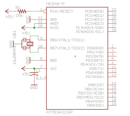
There are many bare-bones Arduinos available on the internet. Most of them are assembled on a solderless breadboard and utilize an ATmega168 (or ATmega328) microcontroller with an Arduino bootloader, a resonator (which may have built-in capacitors or require two...

The diagram illustrates the principle circuit of a radio control car receiver. Important notes include the selection of transistor Q1, which is specified as either 1815 or 9018, along with the bias resistor R1, which has values of 240K...

The National Physics Laboratory broadcasts a time signal, previously known as the Rugby clock but now called "Time from NPL." Its most commonly known as the MSF signal due to it originally being identified in Morse code those letters....