
IR transmitter and receiver

The proposed infrared transmitter-receiver system consists of two main components: the IR transmitter and the IR receiver. The transmitter will emit infrared signals modulated to convey information, while the receiver will detect these signals and activate the connected blue LED accordingly.
The IR transmitter can be constructed using an infrared LED, which emits light in the infrared spectrum when a current flows through it. A microcontroller or a simple oscillator circuit can be used to modulate the signal, allowing for the transmission of data. The modulation can be achieved through techniques such as pulse width modulation (PWM) or frequency modulation, depending on the complexity of the signals to be sent.
The IR receiver typically consists of a photodiode or a phototransistor sensitive to infrared light. When the transmitted IR signal is received, the photodiode generates a small current proportional to the intensity of the incoming light. This signal can be amplified using an operational amplifier to ensure it is strong enough to drive the connected blue LED.
To ensure proper operation, the system should include a power supply appropriate for both the transmitter and receiver circuits. The blue LED will require a current-limiting resistor to prevent it from drawing excessive current, which could damage it. The resistor value can be calculated using Ohm's law, considering the forward voltage drop of the LED and the supply voltage.
In summary, this IR transmitter-receiver system is designed to wirelessly control a blue LED using infrared signals, providing a simple yet effective solution for remote signaling applications.Hi, I wanted to build an IR-transmitter-receiver system to send signals to a device . Let`s say the device is a simple blue LED (just to make life.. 🔗 External reference
Related Circuits
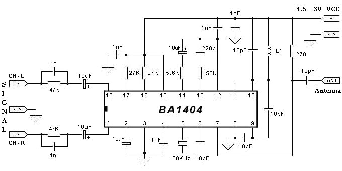
The BA1404 FM stereo modulator IC includes all the necessary components to design a simple, high-efficiency stereo transmitter circuit. It features a stereo modulator that generates composite stereo signals, an FM modulator for creating FM signals, and an RF...
This SMD FM transmitter operates within a frequency range of approximately 80 to 115 MHz. Under optimal conditions, the signal can be received at a distance of around 200 meters. Although it is classified as low-power, its use may...
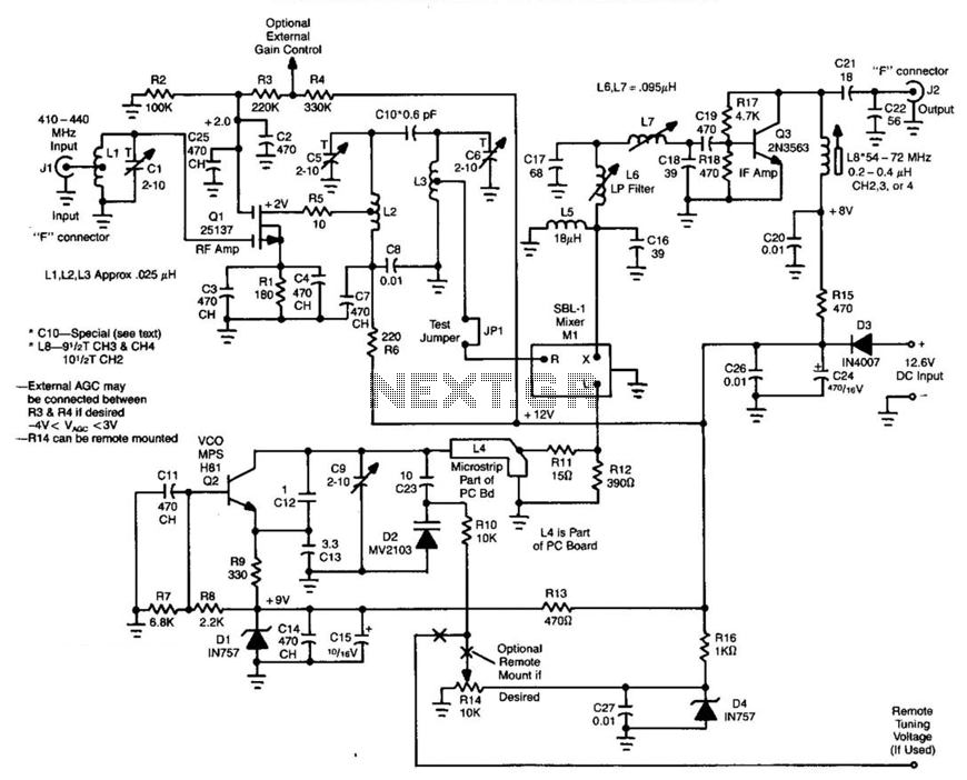
Ll, Ql, L2, and L3 form an RF amplifier stage that feeds Ml, a doubly balanced mixer. Q4 is a local oscillator stage operating in the 375-MHz range. Signals in the 420- to 450-MHz range from Ql are mixed...

The Dish Network 322 Satellite Receiver enables television viewing of two distinct programs in two separate locations. This is a schematic block diagram illustrating an exemplary circuit logic diagram. The receiver is capable of predicting the elevation angle for...
A block diagram and a schematic of the receiver are shown in Figures 2 and 3, respectively. In Figure 3, L6 and L7 are spaced 0.6 inch for a loss of about 0.5 dB. Q4 is the first RF...
This schematic represents an FM transmitter capable of delivering an output power of 3 to 3.5 W, operating within a frequency range of 90 to 110 MHz. While the stability of the circuit is acceptable, the integration of a...