
IRAM109-015SD H-Bridge 1A 500V

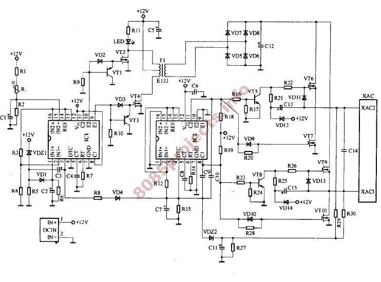
The IR2156 is a versatile integrated circuit designed for driving high-voltage power MOSFETs and IGBTs in half-bridge and full-bridge configurations. One of its critical functionalities is the under-voltage lockout (UVLO) feature, which protects the circuit from operating under insufficient supply voltage conditions.
When the supply voltage (VCC) rises above the UVLO+ threshold, the IR2156 initiates its oscillation process, enabling it to function correctly. This oscillation is essential for the operation of the power stage, as it allows the device to switch the power devices on and off at the desired frequency. The Charge Pump circuit, consisting of components CCP, DCP1, and DCP2, plays a vital role in supplying the necessary current to VCC.
The Charge Pump circuit operates by generating a higher voltage from a lower input voltage, which is particularly useful in applications where the VCC must be maintained above a certain level to ensure reliable operation of the IR2156. The components in the Charge Pump circuit work together to increase the voltage and provide stable current, which is critical for maintaining the functionality of the IR2156 during its operational phases.
In summary, the interplay between the UVLO feature and the Charge Pump circuit is crucial for the reliable operation of the IR2156, ensuring that it functions correctly only when the supply voltage is within safe limits. This combination enhances the robustness and efficiency of power management in various electronic applications.current during under-voltage lockout (UVLO). When VCC exceeds the UVLO+ threshold, the IR2156 BR>begins to oscillate and the Charge Pump circuit (CCP, DCP1, and DCP2) supplies the current to VCC 🔗 External reference
Related Circuits
A schematic for an H-bridge circuit is required to convert a 350V DC input into a 230V AC output at a frequency of 50Hz. The design should utilize a 555 timer integrated circuit (IC) along with MOSFETs. An H-bridge is...
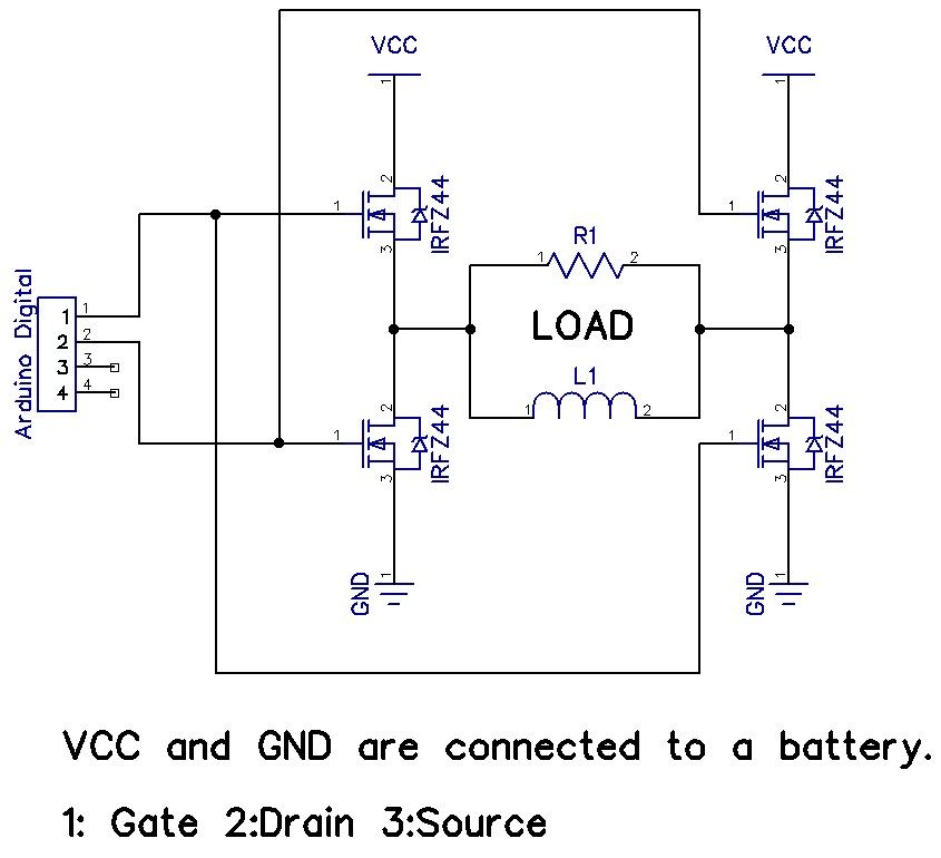
The H-Bridge is a circuit that can drive a motor in both forward and reverse directions. It can be a straightforward circuit that requires only a few components. The H-Bridge circuit is a fundamental configuration used in motor control applications,...
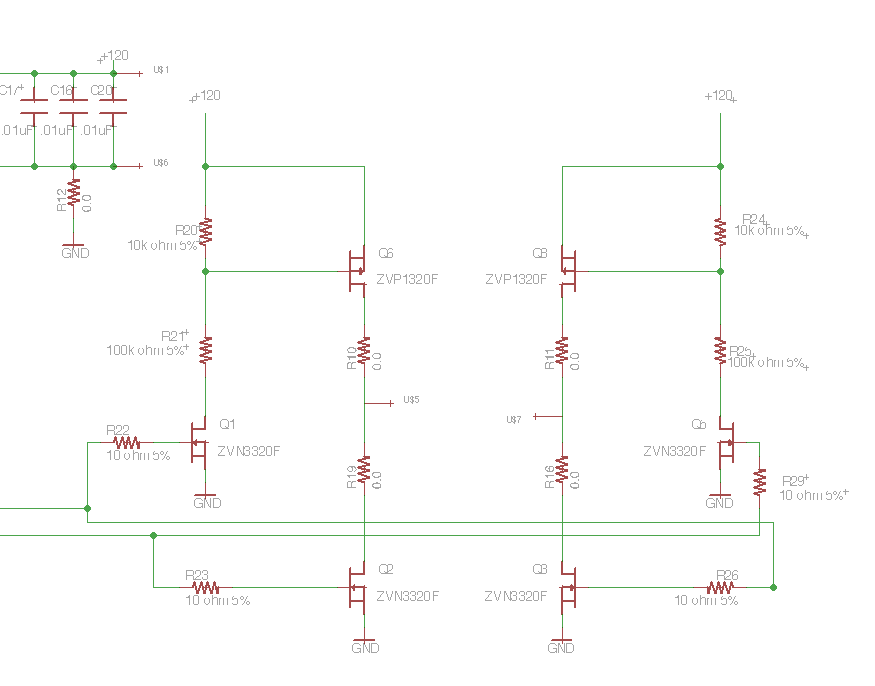
Following the publication of a previous post, some unusual issues were encountered, which required several days to clarify. The main focus was on building a simple Class D amplifier designed to provide an EL panel with a +/- 120V...
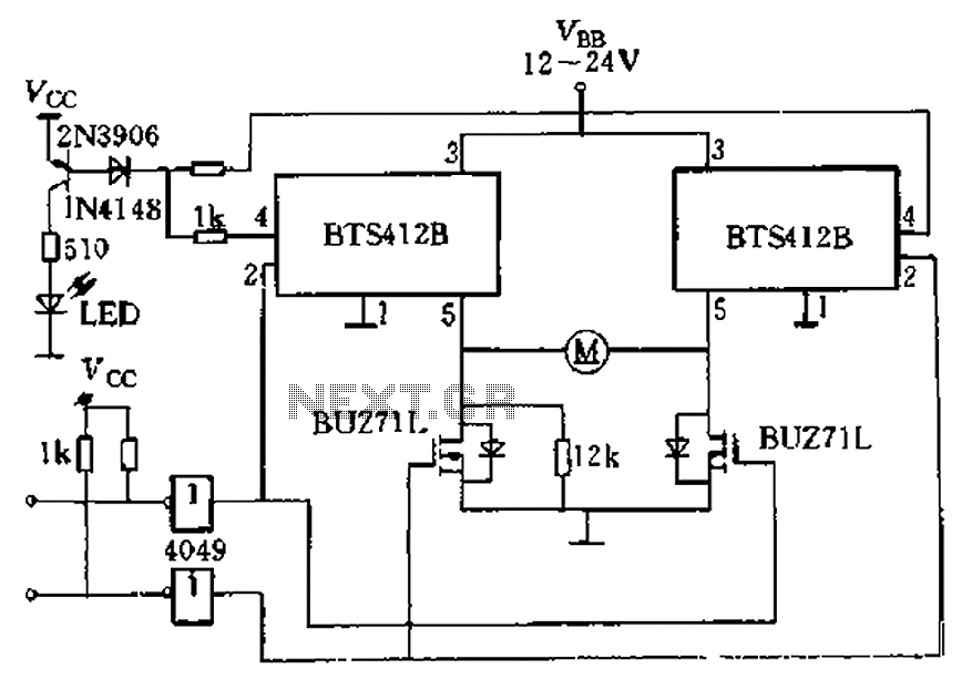
The BTS412B functions as two high-side power MOSFET switches, while two BU271L (50V, Zhang 1n) serve as low-side switches, forming a bi-directional H-bridge DC motor drive circuit. This configuration is designed for electrical automatic door systems, capable of handling...
This circuit operates with a 12V supply connected to a motor, utilizing transistors TIP 142 and TIP 147. Each transistor is controlled by a high (5V) or low (0V) signal through a 1kΩ resistor. The diodes used in the...
This is a slightly revised version of the 6-transistor H-bridge designed by Mark Tilden and found on the BEAM Tek website (now only available via archive). I encourage anyone interested in H-bridges to read Mark's article, as it gives...