
isp flash microcontroller programmer

The ISP Programmer operates by interfacing with the target microcontroller through a series of connections that facilitate programming and debugging. The primary function of the 74245 integrated circuit is to serve as a buffer and isolator for the signals coming from the parallel port of a computer. This ensures that the signals are clean and properly formatted for the microcontroller, minimizing the risk of signal degradation or interference.
The circuit design typically includes several key components beyond the 74245, such as voltage regulators to ensure stable power supply levels, connectors for interfacing with the target device, and possibly additional logic gates or components that may assist in programming operations. The power for the circuit is drawn from the target system, which can vary depending on the specific microcontroller being programmed.
The programmer's software interface allows for easy interaction with the device being programmed. It is crucial that users adhere to the guidelines regarding fuse settings, particularly with devices like the ATmega8, ATtiny26, and ATtiny2313, where incorrect settings can lock the device and prevent further programming through SPI. The datasheet for each specific microcontroller provides essential information on the correct fuse settings and programming procedures, which should be referenced during the setup and operation of the ISP Programmer.
This ISP Programmer is an essential tool for developers working with Atmel microcontrollers, providing a flexible and efficient means of programming and debugging a variety of devices in both in-system and standalone configurations. Proper understanding and adherence to the specifications and guidelines outlined in the respective datasheets will ensure successful programming and operation of the microcontrollers involved.This ISP Programmer can be used either for in-system programming or as a stand-alone spi programmer for Atmel ISP programmable devices. The programming interface is compatible to STK200 ISP programmer hardware so the users of STK200 can also use the software which can program both the 8051 and AVR series devices.
Figure 1 shows the circuit diagram of the in-system programmer interface, the power to the interface is provided by the target system. The 74245 ic isolate and buffer the parallel port signals. The main screen view of the program is shown in figure 3. Also make sure do not program the RSTDISBL fuse in ATmega8, ATtiny26 and ATtiny2313 otherwise further spi programming is disable and you will need a parallel programmer to enable the spi programming. For the fuses setting consult the datasheet of the respective device. 🔗 External reference
Related Circuits
This LED flasher circuit is a classic two-transistor flip-flop. It is a popular circuit often built by beginners in the electronics hobby. The schematic diagram of this well-known LED flasher circuit includes two transistors, two capacitors, four resistors, and...
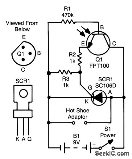
The SCR is connected across the trigger circuit of the flash gun. In its normal state, the SCR remains off, allowing the flash gun to charge to its trigger voltage. A phototransistor, Q1, monitors the light level. When a...

Many battery-powered devices utilize two AA alkaline cells. Often, the user is unaware of when to replace the batteries until the device ceases to operate. The hobby circuit described below can be connected to a 3V battery, providing a...
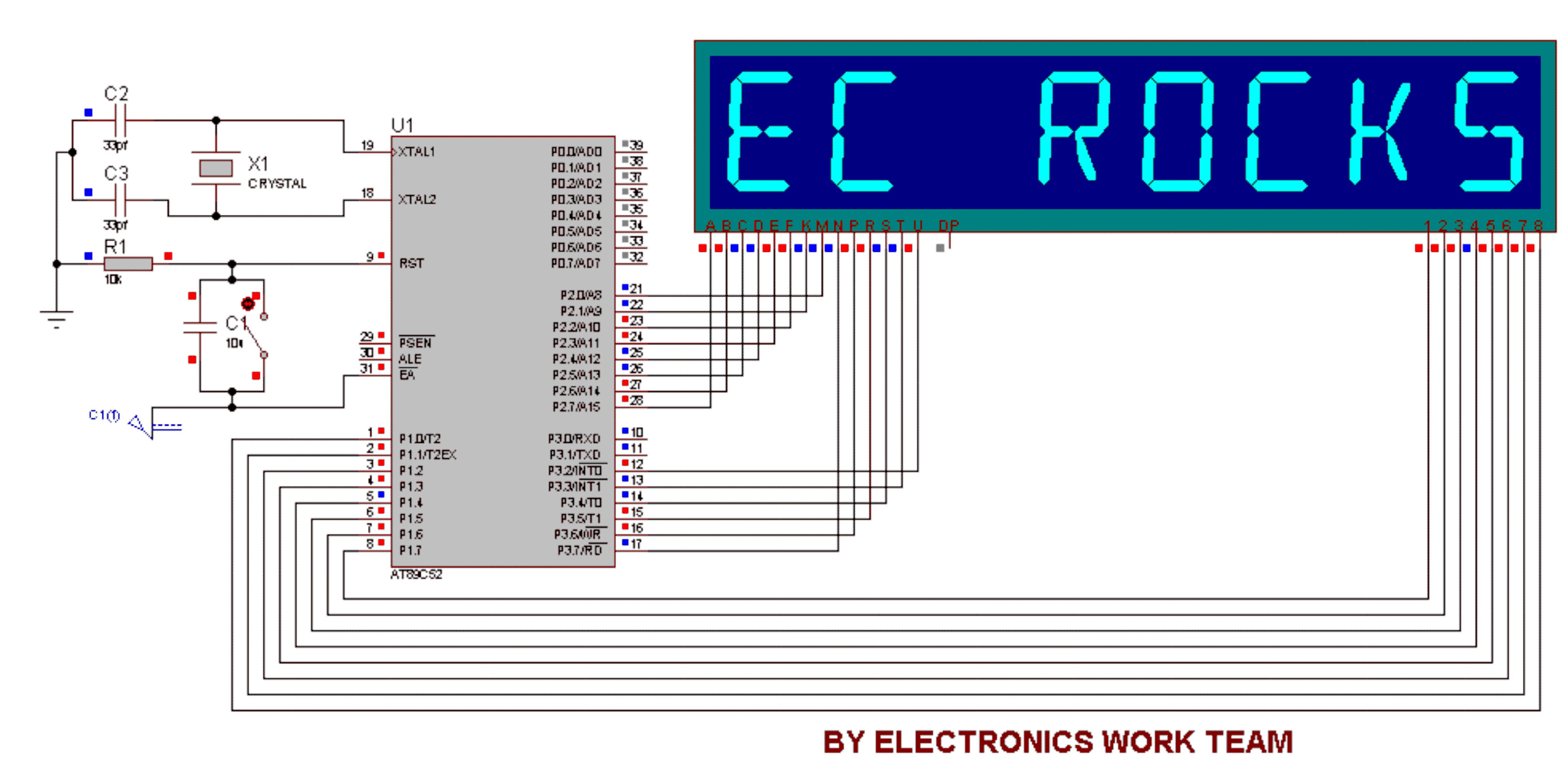
This circuit utilizes a 14-segment display to represent characters. The 14-segment display consists of 22 pins, which facilitate the display of various characters. Eight pins labeled A, B, C, D, E, F, K, and M are connected to the...

Cl, VDI, VD2, C2 form a simple capacitive step-down voltage regulator circuit with a rectifier output providing approximately 8V DC voltage for the LM567. A 5.6-foot manifold is connected. Resistors R3, RP, and capacitor C3 create an ultra-low frequency...

The circuit is built around a single 4093 quad 2-input NAND Schmitt trigger. Two gates from that quad package (U1-a and U1-b) are configured as a set-reset flip-flop. The 4093 integrated circuit (IC) contains four independent 2-input NAND gates with...