
SLAVE FLASH TRIGGER

The described circuit utilizes a Silicon Controlled Rectifier (SCR) as a key component in the triggering mechanism for a flash gun system. The SCR is positioned in parallel with the trigger circuit, ensuring that it remains inactive during the charging phase of the flash gun. This configuration allows the flash gun to accumulate the necessary voltage for triggering without interference.
The phototransistor, Q1, serves as a light sensor that detects the intensity of incoming light. In specific applications, it can be replaced with a GEL14G2 phototransistor, which is suitable for similar functions. When a high-intensity flash is detected, Q1 transitions from a non-conducting state to a conducting state, allowing current to flow through the gate of the SCR. This gate current is essential for the SCR to switch from its off state to its on state, thereby completing the circuit and enabling the triggering of the slave flash gun.
Once the slave flash gun is activated, the SCR must turn off quickly to prevent continuous conduction. This is achieved because the current flowing through the circuit will drop below the SCR's holding current threshold shortly after the flash is triggered. The design ensures that the SCR does not remain latched on, which could lead to unwanted triggering or damage to the circuitry.
The sensitivity of the circuit is adjustable through the resistor R1, which is connected to the base of Q1. By altering the resistance value, the response of the phototransistor to light intensity can be fine-tuned, allowing for customization based on specific operational requirements. A lower resistance value increases sensitivity, making the circuit more responsive to lower intensity flashes, while a higher value decreases sensitivity.
Additionally, the inclusion of a 1-kΩ resistor (R3) between the gate and cathode of the SCR is a critical safety feature. This resistor acts as a protective measure against false triggering, especially in scenarios where high voltages might be present across the anode and cathode. By limiting the gate current under such conditions, R3 ensures that the SCR does not inadvertently turn on, which could compromise the integrity of the entire flash system.
Overall, the circuit is designed to be efficient, responsive, and safe, making it suitable for various applications in photography and lighting systems where precise flash control is essential.The SCR is wired across the trigger circuit of the flash gun. Normally, the SCR is off, so the flash gun is able to charge to its trigger voltage. Photo transistor Q1 is used to monitor the light level. When a high-intensity flash occurs, Q1 briefly con-ducts and supplies gate current to the SCR. That causes the SCR to turn on, which then triggers the slave flash gun via the hot-shoe adapter terminals. 0nce the flash gun has triggered, the SCR`s quickly tums off again. That happens because the current in circuit quickly falls below the SCR`s hold-ing current. The resistor at the base of Q1 (R1)determines the sensitivity of the circuit. If you wish, you can reduce the sensitivity, simply by reducing the value of the resistor from that shown. The 1-k © resistor between the gate and cathode of the SCR (R3) prevents the SCR from false trigger-ing if high voltages are applied between the anode and the cathode.
Q1 can also be a GEL14G2. 🔗 External reference
Related Circuits

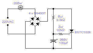
Cl, VDI, VD2, C2 form a simple capacitive step-down voltage regulator circuit with a rectifier output providing approximately 8V DC voltage for the LM567. A 5.6-foot manifold is connected. Resistors R3, RP, and capacitor C3 create an ultra-low frequency...

The microphone inputs connect to ground (-) and to the middle terminal of a 10K variable resistor (potentiometer), which serves as the sensitivity control. The output from the potentiometer is routed to pin 3 of the amplifier integrated circuit...

Flash memory, also known as flash RAM, is a type of non-volatile semiconductor memory device that retains stored data even when not powered. It is an enhanced version of electrically erasable programmable read-only memory (EEPROM). The primary distinction between...

The ADP1649 is a compact and highly efficient single white LED flash driver designed for high-resolution camera phones, enhancing the quality of pictures and videos. The ADP1649 integrates advanced features that optimize the performance of single white LED flash applications....
There is no need to resort to complex circuitry if what you are looking for is a simple power flasher. The light will flash at around 1Hz with a 100W bulb at a duty cycle of 50%. The max....
This circuit functions as a low-frequency warning device. The output from the oscillator generates a square wave signal, which is utilized to operate lamps or small relays. The circuit alternately flashes two incandescent lamps. The low-frequency warning device circuit typically...