
Job Analysis push-pull output

The bootstrap capacitor is a critical component in various electronic circuits, particularly in enhancing the performance of switching converters and amplifiers. It operates by temporarily storing charge and providing a higher voltage to drive the gate of a high-side MOSFET in a half-bridge configuration. This allows the MOSFET to turn on fully, enabling efficient switching and reducing power losses.
In a typical configuration, the bootstrap capacitor C is connected between the supply voltage (V) and the gate of the high-side MOSFET. When the low-side MOSFET is turned on, the voltage at point B drops to ground potential, allowing the capacitor to charge up to the supply voltage. Once the low-side MOSFET turns off and the high-side MOSFET is activated, the charge stored in the bootstrap capacitor raises the gate voltage above the supply voltage, ensuring that the high-side MOSFET is fully enhanced for optimal conduction.
The performance of the bootstrap capacitor is influenced by its capacitance value and the load conditions. A larger capacitance can provide a more stable voltage during operation, especially in applications with rapid switching or variable load conditions. However, it is essential to ensure that the capacitor does not exceed its voltage rating, as this could lead to failure or reduced reliability in the circuit.
In summary, the bootstrap capacitor is integral to achieving high efficiency in power management systems, allowing for effective control of high-side switches in various applications, including motor drives, power converters, and other electronic systems requiring precise voltage regulation and control.A, B, c became indirect person capacitance Figure l-230 new access capacitor C is called the bootstrap capacitor. Self bootstrap capacitor can increase the voltage at point A. When static, Vi- oV, the midpoint voltage VD V +/2, B-point voltage VB VD V +/2, A point voltage hoot v + a VR, the bootstrap capacitor c is A, is charged between B, charging voltage V VA - VB v bucket. A VR + -V/2 v +/VR 2, VR is negligibly small due. When C is large, even if the AC signal voltage by too, the charge voltage V +/2 does not change.
Related Circuits
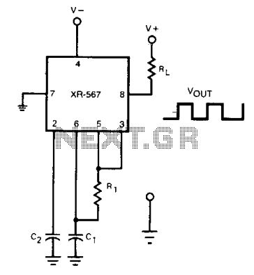
The frequency of the current-controlled oscillator can be doubled by feeding a portion of the square-wave output from pin 5 back to the input at pin 3. This configuration allows the quadrature detector to operate as a frequency doubler,...
This circuit is a variable output switching regulator designed for general-purpose applications. An LM105 positive regulator serves as the amplifier-reference for the switching regulator. Positive feedback to induce switching is derived from the LM105 at pin 1 through an...
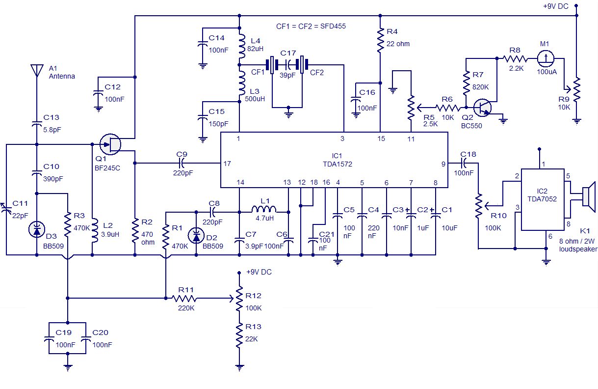
High-quality AM radio circuit based on the TDA1572 IC. The AM radio receiver circuit operates from 9V DC and has a 1W output power. It requires a minimum number of external components. The AM radio circuit utilizing the TDA1572 integrated...
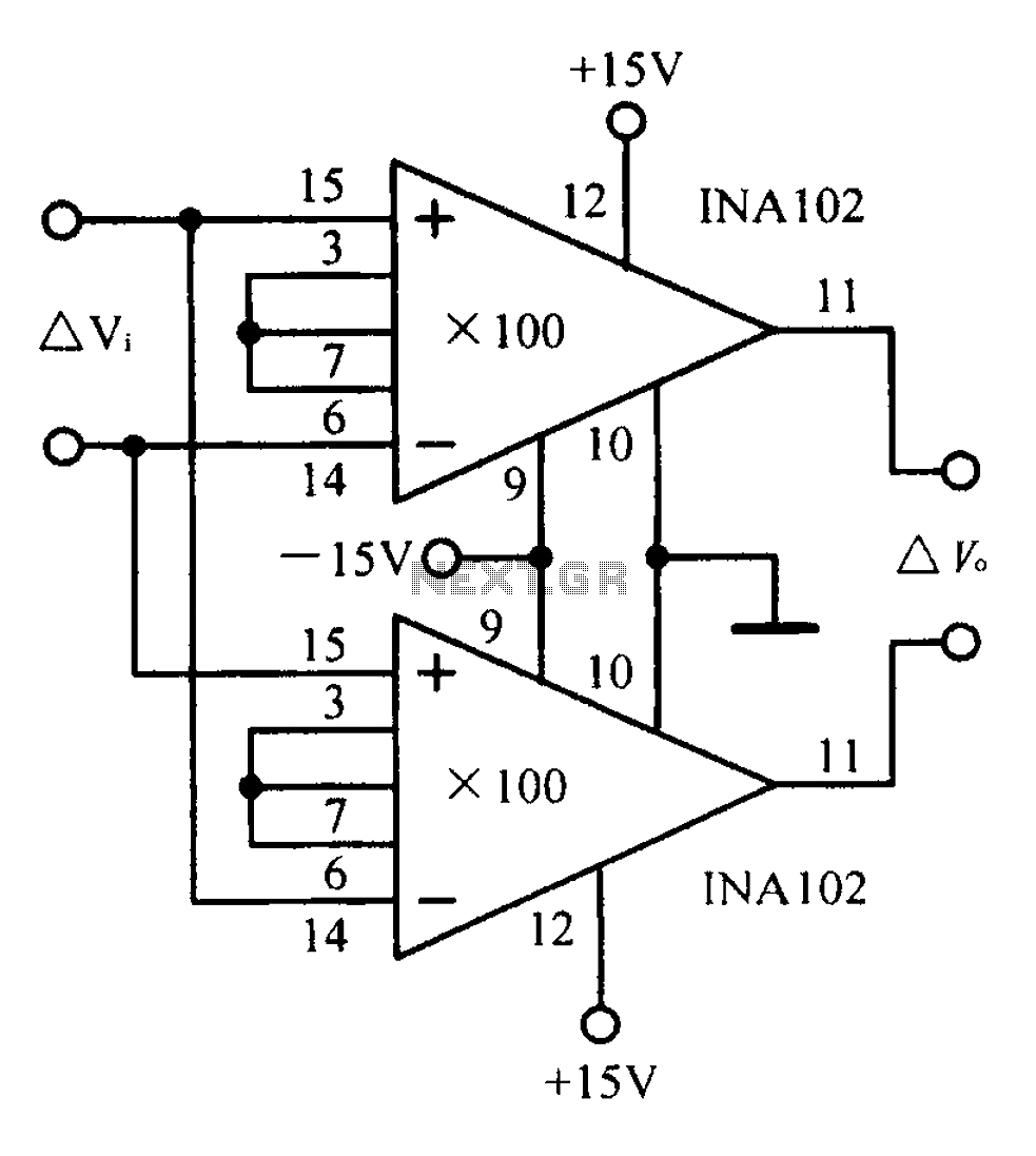
A differential input differential output amplifying circuit diagram. A differential input differential output (DIDO) amplifier is a type of operational amplifier configuration that is designed to amplify the difference between two input signals while rejecting any signals that are common...
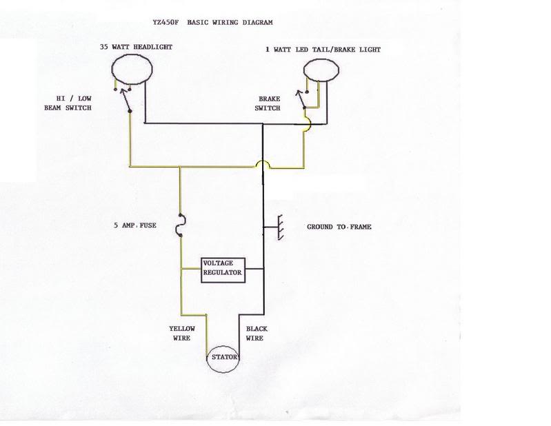
The stator output is alternating current (AC), while a battery operates on direct current (DC). To convert the AC output to DC, a rectifier is necessary, which may result in a loss of 10-15 watts. Although a battery can...
This is a non-contact power regulator circuit designed for a light load. By adjusting a 150kΩ potentiometer, phase shift can be achieved, and a trigger voltage is applied to the gate of a bidirectional thyristor through a bidirectional trigger...