
Construction LED circuit diagram CD4017 CD4011

The circuit is designed to enhance safety awareness in construction environments by utilizing a blinking LED as a visual alert. The primary components of the circuit include a power source, an LED, a resistor for current limiting, and a switching mechanism to control the blinking behavior.
The power source can be a battery or an external power supply, providing the necessary voltage to operate the LED. A resistor is connected in series with the LED to limit the current flowing through it, thereby preventing damage to the LED due to excessive current. The value of the resistor can be calculated using Ohm's Law, taking into consideration the forward voltage drop of the LED and the supply voltage.
To create the blinking effect, a switching mechanism is employed. This could be implemented using a simple transistor circuit or a timer IC such as the 555 timer in astable mode. The timer generates a square wave output that turns the LED on and off at a specified frequency, creating the blinking effect. The frequency of blinking can be adjusted by changing the values of the resistors and capacitors in the timer circuit.
The overall layout of the circuit should ensure that all connections are secure and that the components are rated for the required voltage and current levels. Proper placement of components on a breadboard or PCB will facilitate ease of assembly and troubleshooting. Additionally, incorporating a protective casing for the circuit can enhance durability and safety, especially in a construction site environment.
This LED circuit serves as an effective reminder for safety precautions, making it a valuable addition to any construction site.Construction LED circuit shown in Figure. It requires manual power, after the circuit is powered, the light will blink to remind people to pay attention to safety.
Related Circuits
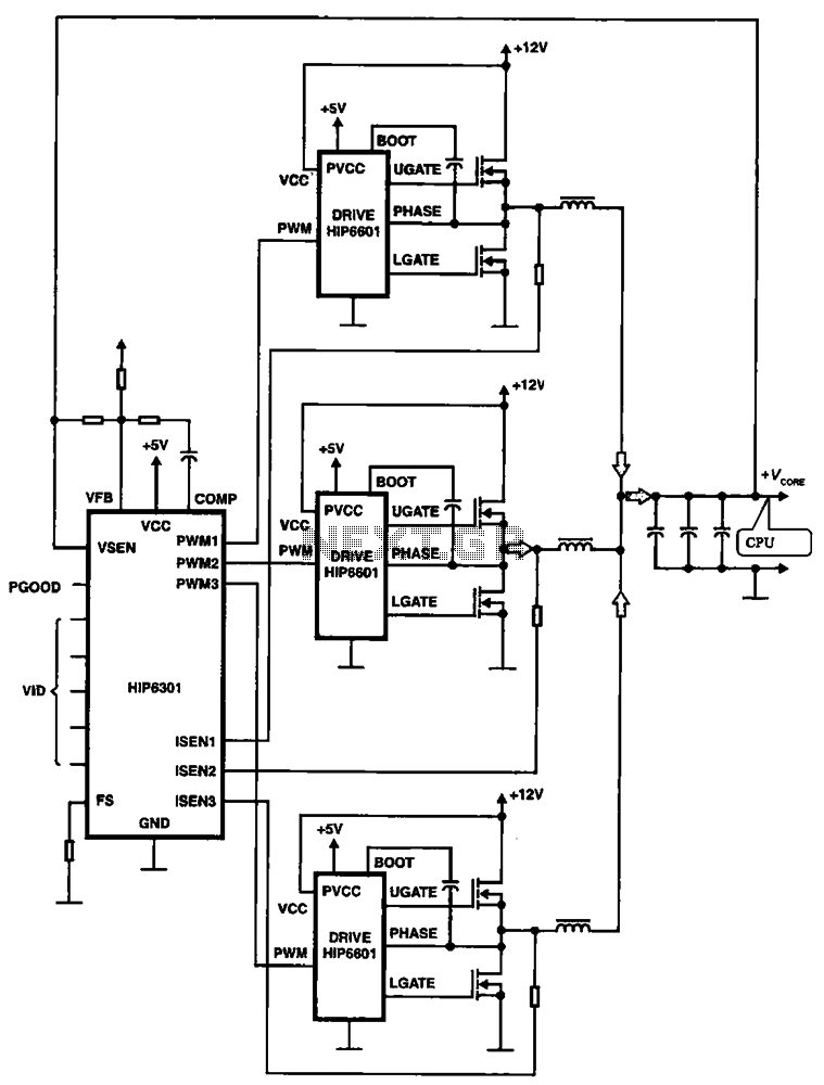
HIP6301 and HIP6601 are used in a 3-phase CPU power circuit. The HIP6301 and HIP6601 are integrated circuits designed for power management in CPU applications, particularly in multi-phase power supply systems. The HIP6301 is a high-performance synchronous buck controller,...
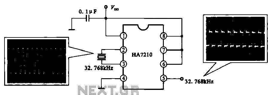
This circuit illustrates a 32.768 kHz micro-power clock oscillator, suitable for use in mobile phones, laptop computers, and home appliances. It generates a clock signal that can be utilized in various applications. The 32.768 kHz micro-power clock oscillator circuit is...
This is a single alarm circuit. The circuit includes automatic exit and entry delays, a timed bell cut-off, and a system reset. It has provisions for normally open and normally closed inputs. The single alarm circuit is designed to provide...
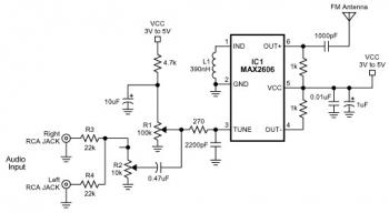
The FM transmitter circuit is built using a single MAX2606 chip. This simple FM transmitter connects a home entertainment system to a portable radio, allowing music to be played in one room and listened to in another, such as...
Circuit audio peak indicator circuit schematics. Circuit Electronics, schematics for audio peak indicator circuit. An audio peak indicator circuit is designed to visually represent the peak levels of an audio signal, providing critical information for audio engineers and musicians regarding...
The liquid level controller circuit comprises a power supply circuit and a level detection control circuit, as illustrated in the accompanying chart. The power supply circuit includes a power switch (S1), a power transformer (T), bridge rectifiers (UR1, UR2),...