
temperature alarm circuit

The circuit employs a Darlington pair configuration, which consists of two transistors connected in such a way that the current amplified by the first transistor is fed into the second transistor. This arrangement provides a high current gain, making it suitable for applications where a small input current needs to control a larger output current. The thermistor, a type of temperature-sensitive resistor, is placed in a voltage divider configuration with the variable resistor. As the temperature rises, the resistance of the thermistor decreases, which alters the voltage across it.
The 12K variable resistor allows for fine-tuning of the threshold temperature at which the circuit activates the buzzer. By adjusting this resistor, the user can set the desired temperature level that triggers the alarm. When the thermistor detects a temperature above this threshold, the resulting change in resistance will lead to an increase in base current for the Darlington pair. This causes the transistors to turn on, allowing current to flow through the buzzer, thus activating it.
In summary, this circuit efficiently combines a Darlington pair of transistors with a thermistor and a variable resistor to create a temperature-sensitive alarm system. The design ensures that the buzzer is only activated when the temperature exceeds a set level, providing a reliable means of monitoring temperature changes.transistors as a darlington pair. The circuit is also using a thermistor to detect or sense the heat. A 12K variable resistor is used to adjust the activation of the buzzer on the desired temperature. Working of the circuit is simple when the thermistor will sense temperature or heat its resistance will become lower due to which the transistors be come switch on and activate the buzzer. 🔗 External reference
Related Circuits

Amplifying circuit diagram to enhance the output current and voltage. An amplifying circuit is designed to increase the amplitude of an input signal, resulting in a higher output current and voltage. This type of circuit is commonly utilized in various...

The relays in the AC arc welding machine manage the load through a three-way power circuit, as depicted in Figure 522. The selected relay type is KA, operating at 24V. Additionally, the time relay KT is of the JS7...

This circuit design was used to switch on device via a LED photocell arrangement (optocoupler) using components R1, C1, D1 and Q1. It produces a delay on powering up to ensure correct sequencing of certain equipment. A very simple...

A mobile phone can be charged using the USB outlet of a PC. This simple USB cellphone charger circuit provides a regulated output of 4.7 volts for charging the mobile phone. The USB outlet typically supplies 5 volts DC...
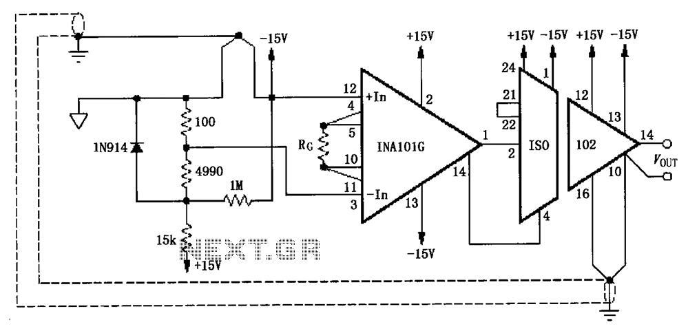
The circuit, as illustrated in the figure, consists of an ISO102 and an INA101 designed to eliminate ground loops and provide high-end cold junction compensation for a thermocouple amplifier. This configuration utilizes a K-type thermocouple to detect temperature at...
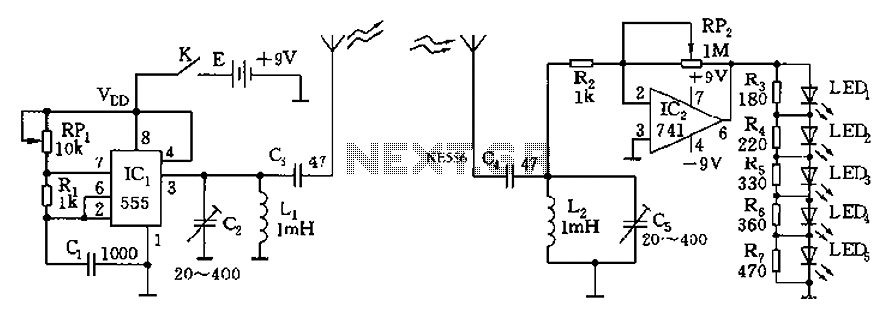
The circuit diagram of the device features a 555 timer IC configured as a transmitter and a receiver, divided into two sections. The 555 timer in the transmitter section serves as the core component of a frequency oscillator. The...