
Morse Keyer circuit

When the paddle is connected to the DOT terminal, C1 starts to charge. When C1's charge reaches sufficiently high value, it causes the transistor BC157B to conduct and pulls the relay and key the transmitter. Paddle connection is then momentarily disconnected through the relay, discharging the capacitor and thus stopping the transistor to conduct. The relay releases and paddle connection is restored to ground. The cycle repeats until the paddle is released. The dash paddle works in the same fashion. The 10 k preset set the dot - dash ratio. The 47 K potentiometer is mounted on the front panel and acts as speed control. 2K2 preset should be adjusted for soft most operation of the keyer. Can you imagine any simpler QRP Keyer?
The described automatic keyer circuit is a basic yet effective design for QRP (low-power) applications, aimed at providing a simple solution for amateur radio enthusiasts. The primary components include a capacitor (C1), a transistor (BC157B), and a relay, which work synergistically to create a reliable keying mechanism for a transmitter.
The operation begins when the paddle is connected to the DOT terminal. The capacitor C1 begins to charge through the paddle, and once the voltage across C1 reaches a predetermined threshold, the BC157B transistor is activated. This conduction of the transistor energizes the relay, which in turn connects the transmitter, allowing it to send a signal. The relay momentarily disconnects the paddle from the circuit, allowing C1 to discharge. As the capacitor discharges, the transistor ceases conduction, causing the relay to release and reconnect the paddle to ground. This cycle of charging and discharging continues as long as the paddle is pressed, enabling the user to send Morse code signals.
The dash paddle operates on a similar principle, ensuring that both dot and dash signals can be generated effectively. The circuit includes a 10 kΩ preset resistor that adjusts the dot-dash ratio, allowing for customization based on the operator's preference. Additionally, a 47 kΩ potentiometer is incorporated into the design, mounted on the front panel, to serve as a speed control for the keyer. This feature allows users to adapt the keying speed to their comfort level and proficiency in Morse code.
Furthermore, a 2.2 kΩ preset resistor is included in the circuit to fine-tune the operation of the keyer, ensuring that it functions smoothly and responsively. This simplicity and ease of construction make the keyer an attractive project for those interested in QRP operations, providing an accessible way to engage with Morse code transmission. Overall, the design embodies a straightforward approach to automatic keying, with an emphasis on user-friendly features and effective performance.This is not a sophisticated automatic keyer but it is lot QRP to build and to have fun operating it. When the paddle is connected to the DOT terminal, C1 starts to charge. When C1's charge reaches sufficiently high value, it causes the transistor BC157B to conduct and pulls the relay and key the transmitter. Paddle connection is then momentarily disconnected through the relay, discharging the capacitor and thus stopping the transistor to conduct.
The relay releases and paddle connection is restored to ground. The cycle repeats until the paddle is released. The dash paddle works in the same fashion. The 10 k preset set the dot - dash ratio. The 47 K potentiometer is mounted on the front panel and acts as speed control. 2K2 preset should be adjusted for soft most operation of the keyer. Can you imagine any simpler QRP Keyer? 🔗 External reference
Related Circuits
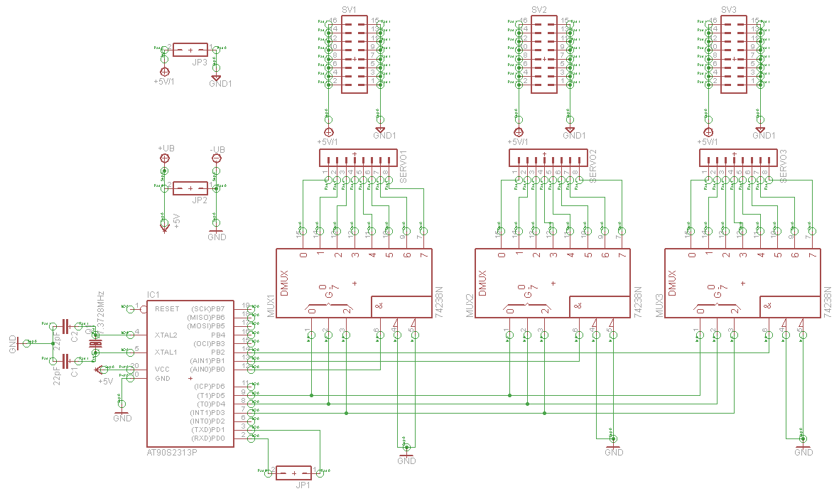
A serial servo controller is being developed to enhance knowledge of electronics and assembly language as part of a hexapod robot project. Initially, the ATTiny2313 microcontroller was utilized; however, it became evident that additional I/O channels were necessary. Consequently,...

A simple touch dimmer circuit diagram using the TT6061 IC, which is a touch control integrated circuit used for light dimmer circuits and lamp dimmer circuits. The touch dimmer circuit utilizing the TT6061 IC is designed to provide a user-friendly...
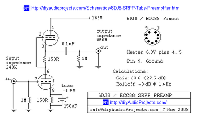
This is one of many available variations for a Symmetrical SRPP Preamplifier based on the 6DJ8 / ECC88 family of tubes. The SRPP circuit has also been referred to as a SEPP, Totem Pole, Mu Follower, Mu amplifier, and...
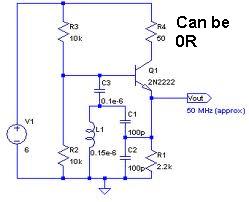
An oscillator circuit capable of generating a high-quality sine wave with a frequency of at least 500 MHz, intended for RFID applications. There have been attempts to utilize a class E oscillator, but the design has not yet been...
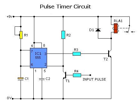
Today, solutions are offered for a timed control relay that utilizes Normally Open (NO) and Normally Closed (NC) contacts to manage the operation of other devices, enabling or disabling them as needed. The functionality of this circuit is based...
You may be familiar with this effect. You switch audio equipment such as an amplifier to a different input and there is a loud click or "thump" in the speaker system. Not all equipment is affected. Some high-end audio...