
DC fluorescent light circuit

The circuit operates by utilizing the principles of oscillation to deliver the necessary voltage and current to ignite the fluorescent lamp. The oscillator, formed by the transistor VT, generates a square wave signal that drives the transformer. The transformer steps up the voltage, allowing for the initial ignition of the fluorescent lamp. The configuration of the windings is critical; the primary winding (W1-W2) with 40 turns is designed to create a magnetic field that induces a higher voltage in the secondary winding (W3).
The selection of the capacitor (C) is crucial as it determines the oscillation frequency. An increase in capacitance results in a lower frequency, while a decrease raises the frequency. This frequency modulation is vital for achieving the desired performance of the ignition circuit. The resistors in the circuit provide necessary current limiting and stabilization for the transistor, ensuring reliable operation within specified limits.
For optimal performance, the use of ferrite core materials in the transformer is recommended. Ferrite cores exhibit high magnetic permeability, which enhances the efficiency of the transformer and minimizes energy losses. The winding specifications, including the wire diameter, are chosen to balance current carrying capacity and inductance, further contributing to the circuit's overall efficiency.
In summary, this ignition circuit for a DC fluorescent lamp is a carefully designed oscillator circuit that leverages transformer action and component selection to achieve reliable lamp ignition and operation. Proper implementation of the winding turns, capacitance, and resistance values is essential to ensure maximum efficiency and performance.For the use of direct current 6 ~ 8W fluorescent lamp ignition circuit ring. It is a common emitted by a pole blocking oscillator consisting of VT, induced by the secondary side of the transformer in an intermittent oscillation crossing, fluorescent light. The actual application of the test, when the power supply voltage is DC 12V, the lamp ignited after continuous voltage 5zv.
If the supply voltage switch to 6V DC, the transformer secondary winding turns W3 of 1600 should be increased to 450 turns turns. R Available 0.25W or 0,125W resistance, capacitance C from o. Choose between 1 ~ lFcF. C value change between intermittent oscillator frequency is also changed. Select the appropriate value of C, the circuit allows maximum efficiency. Preferably with an E type ferrite transformer. Wl-WZ - 40 turns, diameter of 0.35 mm; W3-450 turns, diameter of 0.121mm.
Related Circuits
An automatic multipurpose emergency lights circuit is presented. Typically, emergency lights are connected to the mains for standby when fully charged. In the event of a sudden power failure, the ambient light transitions from strong to weak, indicating a...
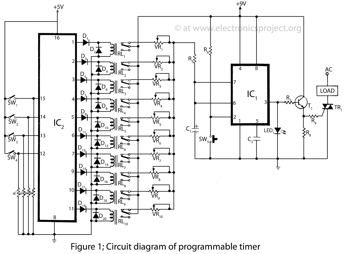
The programmable timer presented on this website is a straightforward design utilizing only two integrated circuits (ICs). It covers a wide range of applications and includes descriptions of various timer projects. The programmable timer circuit typically consists of two primary...
This circuit below shows a teleremote circuit that enables the switching on and off of appliances through telephone lines. The teleremote circuit utilizes a telephone line as a medium for controlling electrical appliances from a distance. The primary components...
Here is a simple circuit which can be used for decoration purposes or as an indicator. Flashing or dancing speed of LEDs can be adjusted and various dancing patterns of lights can be formed. The circuit consists of two...
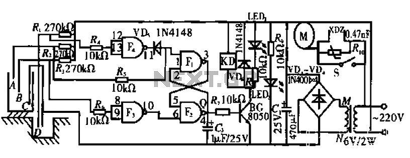
The circuit operates by monitoring the water level in a tank. When the water level falls below a specified point (F), the RS flip-flop (F2) is activated, producing a high Q output that energizes a relay to start the...
is circuit was requested from an email. It will allow your car headlights to flash on and off at the same time or it will cause them to flash alternately. The circuit is based on the 555 timer. It...