
Keypad Talking To LCD Via AT89S51

The schematic involves a typical setup for interfacing an AT89S51 microcontroller with an LCD and a keypad. The AT89S51 is an 8-bit microcontroller based on the 8051 architecture, featuring 4KB of ROM, 128 bytes of RAM, and several I/O ports. The LCD used is typically a 16x2 character display, which requires a set of control and data lines connected to the microcontroller.
The interface begins with connecting the LCD's RS (Register Select), RW (Read/Write), and E (Enable) pins to designated I/O pins on the AT89S51. The data pins D0 to D7 of the LCD are also connected to the microcontroller's I/O pins. A potentiometer is connected to the V0 pin of the LCD to control brightness, allowing the user to adjust the display contrast.
The keypad is typically a 4x4 matrix, requiring a set of rows and columns to be connected to the microcontroller. Each key press connects a specific row and column, which the microcontroller detects by scanning the rows and columns. The microcontroller's firmware is responsible for managing the scanning process, detecting key presses, and sending the corresponding character to the LCD for display.
Power supply for the entire circuit is provided at 5 volts, which is a standard operating voltage for both the AT89S51 microcontroller and the LCD. It is crucial to ensure stable voltage levels to avoid erratic behavior in the components. The assembly code uploaded to the microcontroller should include routines for initializing the LCD, handling keypad input, and updating the display accordingly.
Testing the system involves verifying that the LCD displays the correct character corresponding to the key pressed on the keypad. This comprehensive approach ensures that each component is functioning correctly and that the overall system operates as intended.In few previous post, I showed schematic for interfacing Keypad and LCD using 8051 architecture. This blog post shows complete implementation of the interface using AT89S51 Micro-controller with programming in assembly. Considering that one understands the technical background for Keypad and LCD. Now, follow the schematic given above and solder th e components on the General Purpose PCB : Note : While doing so, first solder LCD and check if it works properly by uploading the code to display the characters and the move on to Keypad phase. Doing in phases helps. Now cross check the connections and also make sure that LCD`s brightness is controllable with the pot when the system in powered using a power supply.
Supply voltage in this case was 5 Volt. Next step is to upload the code for capturing Keypad data and to display same on the LCD. I would encourage individuals to write the code on own, hence not sharing here. And after the code has been burned, place the AT89S51 on IC socket and test the system, whichever key is pressed that key should be displayed on the LCD : 🔗 External reference
Related Circuits
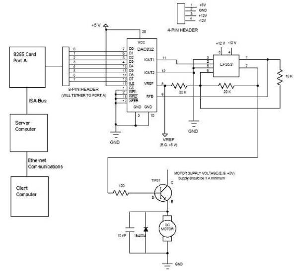
Open loop speed control of a DC motor is implemented using the 8255 Digital I/O Controller chip in conjunction with a TCP/IP server-client application programmed in Visual Basic. The DAC0832 chip serves as the Digital to Analog Converter. This...
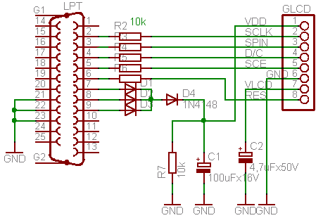
This circuit is designed to drive a Nokia 3310 graphical LCD using a simple LPT cable and associated PC software. The graphical LCD requires a supply voltage of approximately 3.3V, while the LPT port provides a voltage range of...
The circuit design aims to create a preamplifier for television systems that operates within the UHF frequency range of 450 MHz to 800 MHz. The preamplifier circuit is essential for enhancing weak television signals before they are processed by the...
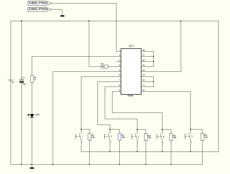
This project can be used for many different purposes. Probably the most used application would be to interface to any electronic project that requires a keypad. There are several ready made keypads on the market, but those work with...
An alphanumeric low-cost LCD display is essential for many small and large projects to display various types of information. The Hitachi HD44780 chipset-based 16x2 character LCD is very affordable and easily available in the local market. This project covers...
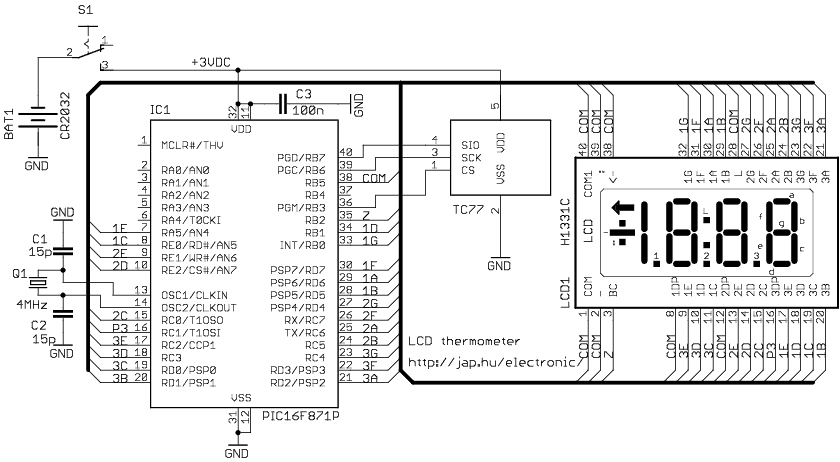
The circuit drives the LCD pins with 50% square waves. Each segment on this LCD is connected to the COM backplane and a separate pin. When a pin is driven in phase with the COM pin, the corresponding LCD...