
Laboratory Power Supply

In the context of electronic schematics, the concept of transmitting information can be likened to the process of data communication systems, where various components work together to ensure the effective transfer of information. This can involve a combination of analog and digital components, depending on the nature of the data being transmitted.
A basic electronic schematic for a data communication system might include a microcontroller as the central processing unit, responsible for managing data flow. This microcontroller can interface with a variety of input devices, such as sensors or user interfaces, to gather information that needs to be transmitted.
The data can then be processed and sent through a communication module, such as a Wi-Fi or Bluetooth module, which enables wireless transmission. The schematic would include power supply components to ensure that all devices operate within their specified voltage and current ranges.
Additionally, to address potential issues such as data integrity and security, the schematic may incorporate error detection and correction circuits, as well as encryption modules. These components work together to ensure that the transmitted information remains accurate and secure, minimizing the risk of copyright infringement or content-related issues.
Overall, the electronic schematic for a data communication system is designed to facilitate the seamless transmission of information while addressing potential challenges that may arise during the process.We aim to transmit more information by carrying articles. Please send us an E-mail to wanghuali@hqew. net within 15 days if we are involved in the problems of article content, copyright or other problems. We will delete it soon. 🔗 External reference
Related Circuits
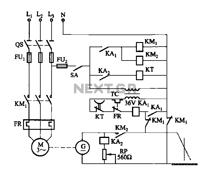
The DC arc welding machine is connected to the secondary load path of the power circuit as illustrated in the figure. This circuit is designed for use during extended downtime, approximately lasting a few minutes, and is not suitable...

The unit is designed around a standard operational amplifier and utilizes easily obtainable components. The reverse-engineered circuit diagram of the Anatek 50-1S variable power supply is shown below. The layout of the circuit board does not appear to be...
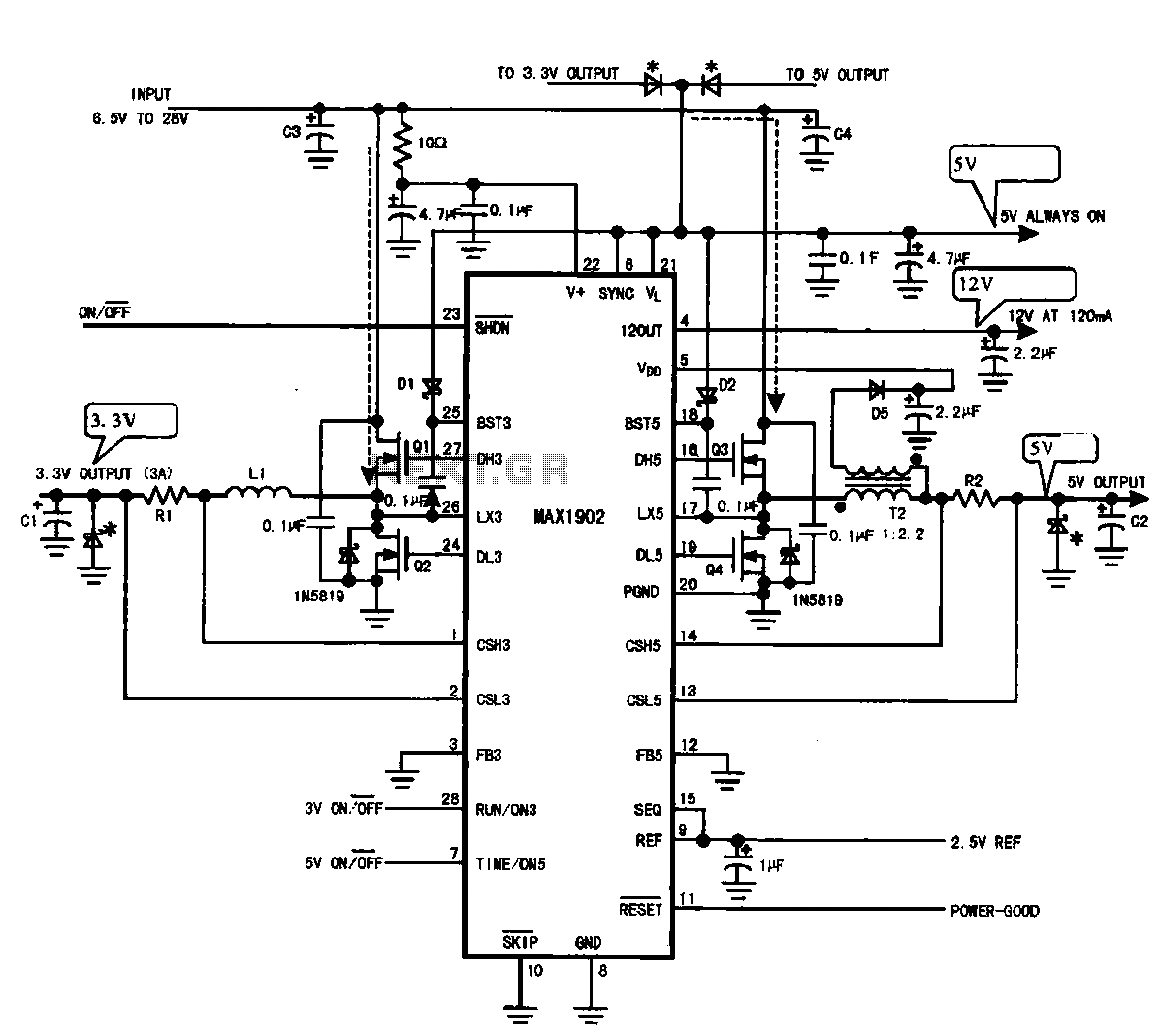
Multi-output power supply circuit (MAX1902). This circuit illustrates the power supply configuration for a notebook computer motherboard, utilizing the MAX1902 chip for power control. It is designed to convert the battery's DC voltage into multiple DC voltage outputs. The multi-output...
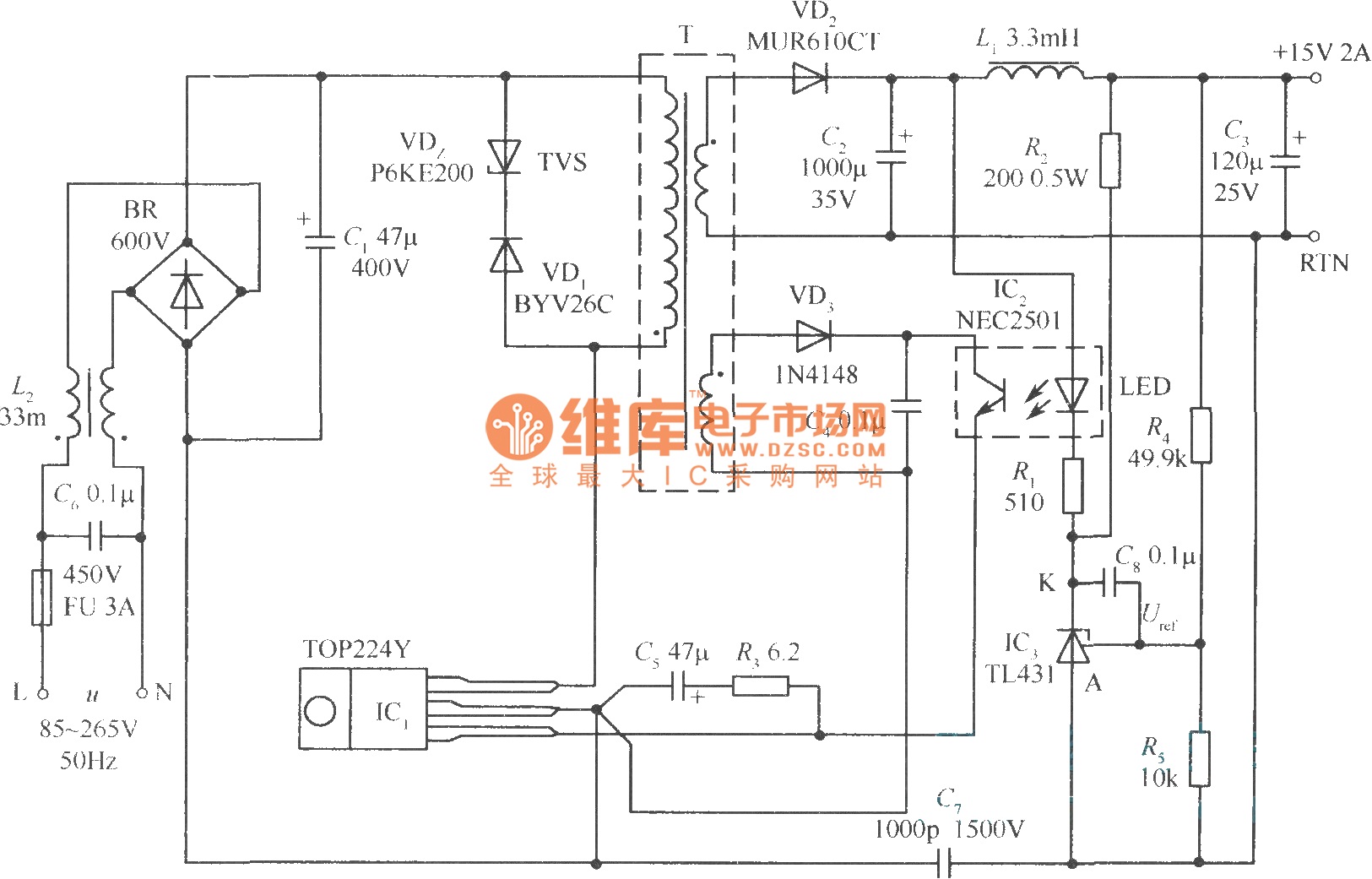
This document presents a 30W micro switch regulated power supply utilizing the TOP224Y integrated circuit. The circuit diagram illustrates its design. A notable feature of this power supply is the use of the TL431 component to replace the regulation...
This is a simple circuit for automatic switchover between battery and USB port. This circuit uses a more general step-up converter architecture. The circuit designed for automatic switchover between a battery and a USB power source employs a step-up...
Following a hunch, the author discovered (or re-discovered?) that all plants carry an electric charge relative to the ground. This charge is more or less constant regardless of the size of the plant - a kind of "background voltage"...