
Anatek Lab Supply

The Anatek 50-1S variable power supply circuit is based on a straightforward operational amplifier configuration, which serves as the core of the voltage regulation system. The design incorporates a feedback loop that stabilizes the output voltage while allowing for variable adjustments. The op-amp is configured in a non-inverting mode, where the reference voltage is set using a potentiometer, enabling fine-tuning of the output voltage.
The power supply utilizes a transformer with dual output windings, providing the necessary AC voltage for rectification and regulation. The rectification stage typically employs a bridge rectifier, converting the AC voltage to pulsating DC, which is then smoothed using filter capacitors. The choice of transformer size can vary, as the circuit is adaptable to both larger and smaller transformers, maintaining functionality regardless of the transformer’s power rating.
The circuit board layout is designed with flexibility in mind, allowing for variations in component placement without significant impact on performance. The separate connectors for sense wires ensure accurate voltage sensing at the load, minimizing voltage drop caused by wiring resistance.
The operational amplifier's pin 8 serves as a crucial test point, indicating when the circuit is in current-limited mode. This feature is essential for protecting sensitive loads from excessive current, and the high signal at this pin can be used to drive an LED, providing a visual indication of the current limiting status. Overall, the Anatek 50-1S variable power supply is a robust and versatile design suitable for a range of applications, leveraging common components and straightforward circuit principles.The unit is designed around an ordinary op-amp and easy to obtain parts. Reverse engineered circuit diagram of Anatek 50-1S variable power supply shown below. Circuit board layout does not seem all that critical and as you can see from the schematic that sense wires to the circuit board have their own stake on connectors separate from the output w ires. Although the unit uses a single transformer with two output windings the circuit works equally well using a big transformer and a little transformer. The test point at pin 8 of the op-amp goes high when the variable power supply is operating in current limited mode and it could be used to drive an LED.
🔗 External reference
Related Circuits
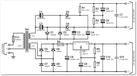
Many later radios utilize four 7-pin valves and require a high tension (HT) supply of 90V at approximately 12mA, and a low tension (LT) supply of either 125mA or 250mA, depending on the specific valves used. The original batteries...
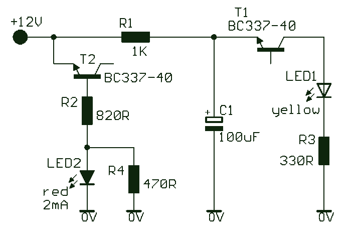
This simple and slightly odd circuit can clearly show the level of the supply voltage (in a larger device): as long as the indicator has good 12 volts at its input, LED1 gives steady, uninterrupted (for the naked eye)...
In Capacitor Power Supplies, a Voltage Dropping Capacitor is used in series with the phase line. Ordinary capacitors are unsuitable for these applications because mains spikes can create holes in the dielectric of standard capacitors, leading to failure. This...
This contributed project is a result of considerable collaboration between Sergio and myself, and should not be seen as necessarily a complete project in itself, but a stepping stone to understanding switching power supplies, how they work, and what...
A power transistor with a voltage drop of 4 volts and a current of 3 amps may dissipate approximately 12 watts of heat, presenting a challenge in series regulators. In contrast, a saturated transistor or MOSFET with a voltage...
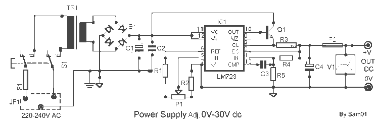
It is a simple circuit regulated power supply, based on the known LM 723, that drives a transistor Q1 [2N3055]. The regulation of voltage, of expense becomes with potentiometer R1 from 0v-30v DC roughly. In order to achieve 30...