
Lamp Flasher

The described circuit functions as a flasher for continuous light lamps, transforming them into flashing lights. It is particularly effective for automotive applications and panel indicators, capable of driving loads up to 10 watts. The circuit operates within a voltage range of 3 to 24 volts DC, making it versatile for various applications involving existing on-circuit lamps.
To implement this circuit, the existing negative supply connection to the lamps must be interrupted. The circuit is then inserted between the lamp's connection and the negative supply. It is critical to maintain the correct polarity during installation to ensure proper operation and prevent damage to the components.
The circuit utilizes a capacitor, denoted as C1, which plays a pivotal role in determining the flashing frequency of the lamps. The capacitance value of C1 can be adjusted between 100 µF and 1000 µF or even higher, allowing for customization of the flashing rate. A larger capacitance will result in a slower flashing rate, while a smaller capacitance will yield a faster flashing effect. This adjustability provides flexibility in design, accommodating different visual requirements for the application.
In addition to standard incandescent lamps, the circuit is also compatible with LED lamps, expanding its usability in modern lighting applications. When using LEDs, consideration must be given to their forward voltage and current ratings to ensure that the circuit operates within safe limits.
Overall, this flasher circuit is a practical solution for converting static lighting into dynamic signaling, enhancing visibility and alertness in various environments. Proper installation and component selection are essential for optimal performance and reliability.This circuit was designed to provide that continuous light lamps already wired into a circuit, become flashing. Simply insert the circuit between existing lamp and negative supply. Especially suited for car or panel pilot lights, this device can drive lamps up to 10W. Ideal to operate 3 to 24V DC existing on-circuit lamps. LED operation is also possible. * Break lamp(s) to negative supply connection(s), then insert the circuit between existing lamp(s) connection(s) and negative supply (respecting polarities!). * C1 value can be varied from 100 to 1000µF or higher, in order to change flashing frequ 🔗 External reference
Related Circuits
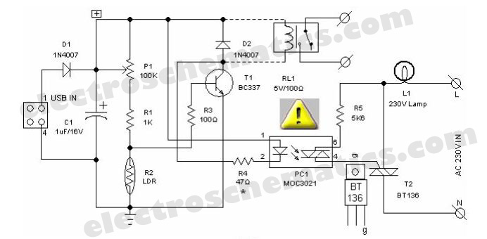
Most of the PC desk lamps available in the market illuminate whenever there is input power. These do not consider whether there is an actual need for light. The typical design of PC desk lamps operates on a straightforward principle:...
is circuit was requested from an email. It will allow your car headlights to flash on and off at the same time or it will cause them to flash alternately. The circuit is based on the 555 timer. It...
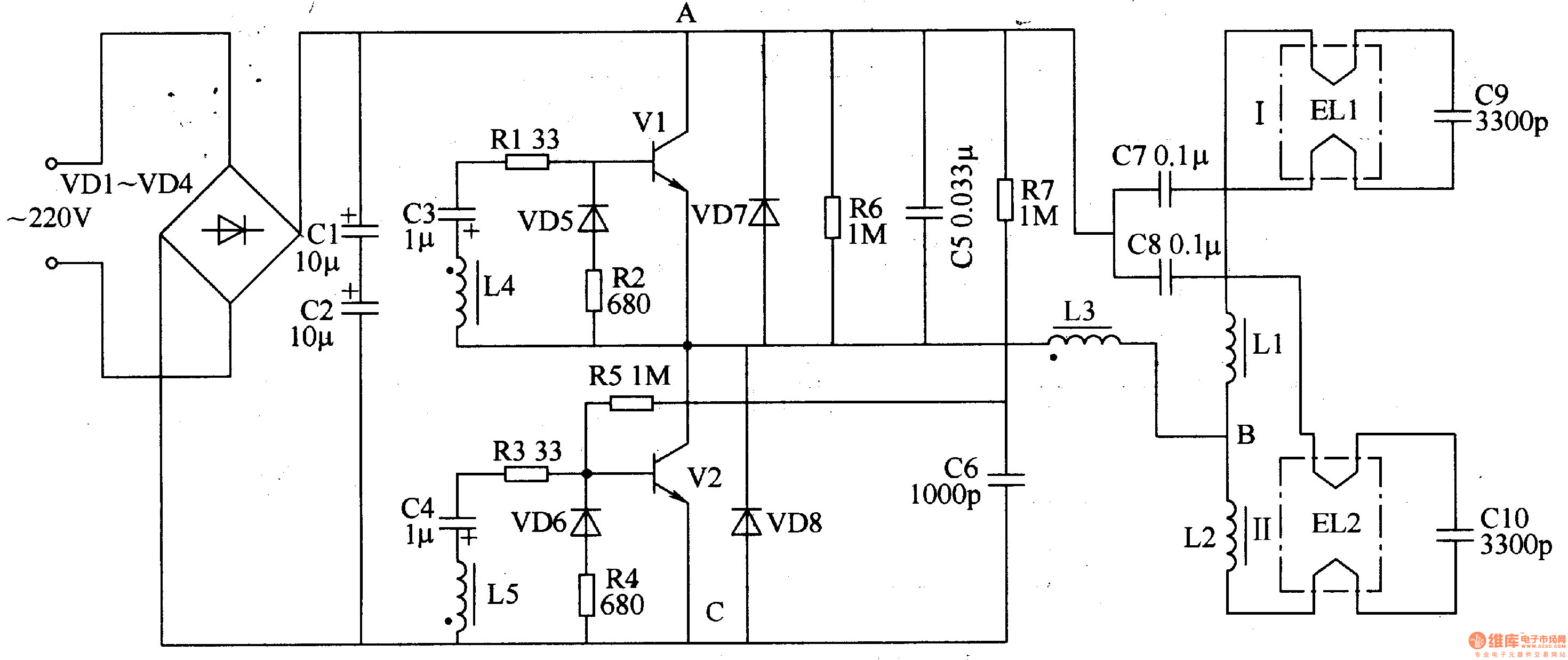
The electronic ballast circuit for fluorescent lamps comprises a rectifier filter circuit, a high-frequency oscillator circuit, and an output circuit, as illustrated in Figure 3-202. The rectifier filter circuit consists of rectifier diodes VD1-VD4 and filter capacitors C1 and...
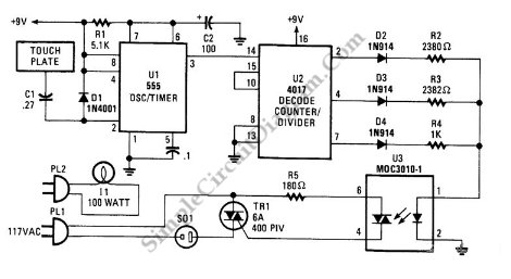
This is a three-mode lamp dimmer circuit with touch control. This circuit can be used to control a lamp in three operation modes: dim, off, and bright. A NE555 timer is utilized in the design. The three-mode lamp dimmer circuit...
This is a simple LED flasher using two 2N3904 transistors. Classic astable multivibrator using 2 transistors. Transistor is not critical. Try these: 2N4401, 2N2222, NTE123A, NTE123AP, NTE159, TUP/TUN and those in your junk box, you may find that most...
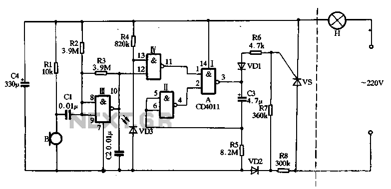
The main circuit utilizes a two-input NAND gate composed of four digital integrated circuits. This includes a NAND gate microphone amplifier circuit, a light control mechanism using an "AND gate," and a monostable delay control circuit formed by NAND...