
LAN RJ45 Cable Connection Tester

The circuit operates by sequentially activating each output pin to send a pulse through the LAN cable. The main board contains a microcontroller, such as the AVR ATtiny2313, which is programmed to generate a series of pulses. The design ensures that only one output is active at any time, creating a clear and distinct signal that travels through the connected LAN cable.
When a straight LAN cable is used, the signal travels directly from one connector to the other, illuminating the LEDs in the order they are connected. This allows for a straightforward visual indication of the cable's integrity. If any of the internal wires are broken, the corresponding LED will remain off, indicating a fault in the cable.
In contrast, when a cross-over cable is connected, the internal wiring configuration changes the path of the signals, resulting in a different sequence of illuminated LEDs. This change can be utilized to quickly identify the type of cable being tested without the need for additional equipment.
For remote testing, the circuit can be extended using a secondary board equipped with LEDs. This remote unit connects to one end of the LAN cable, while the main board remains at the other end. The design of the remote unit eliminates the need for a common ground wire, simplifying the connection process.
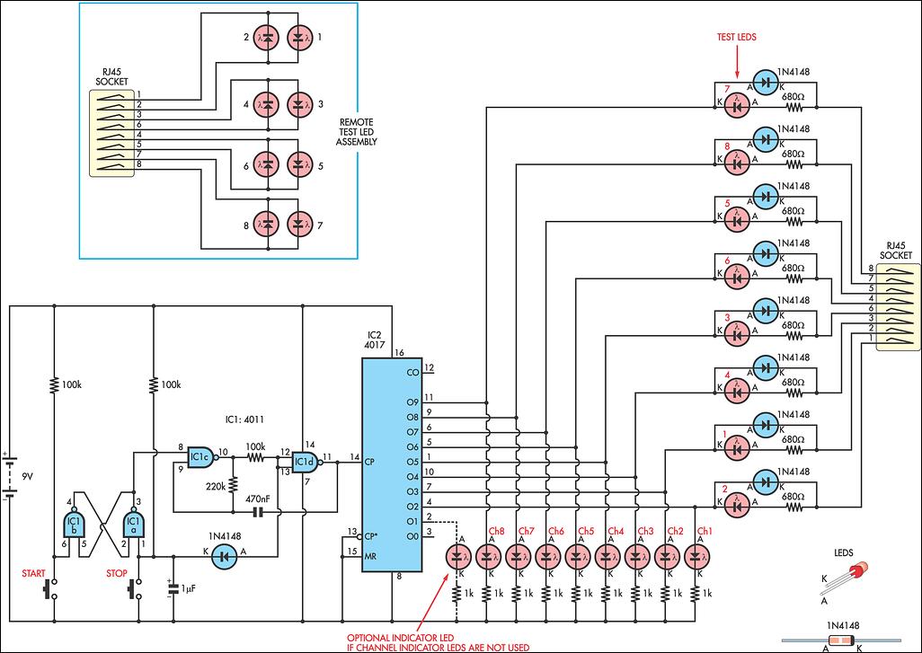
This circuit is not only useful for checking LAN cables but can also serve as an educational tool for understanding the differences between straight-through and cross-over cables. The use of an AVR microcontroller allows for flexibility in design and the potential for further enhancements, such as incorporating additional features or a more sophisticated user interface.Here`s a very simple, but practical circuit, which is used to check the type of LAN cables (straight or cross) as well as possible faults. So we use a unit that has 8 outputs, each one of which produces a pulse successivly. Only one output can be high at any time. Then we use two rj45 connectors and we apply the pulses to the 8 pins of one connect or (A) wnd we connect LEDs at the pins of the other connector (B). If we connect a straight LAN cable, we notice that the LEDs glow one by one successively. If a wire is broken, the coresponding LED will not glow. Just watch the LEDs. If we connect a cross wire, then the order of LEDs glowing changes to 1, 2, 7, 4, 5, 8, 3, 6. So we can laber the LEDs in that order, so that we can watch easily. If both ends of the cable are not close enough to be pluged onto the curcuit, we can use an remote board, which has only one rj-45 connector and 8 LEDs. Then plug one end of the cable to connector A on main board and connect the other end to the remote unit.
Notice that no common wire is needed for the remote unit. I have included an alternative circuit instead of using classic ics, I use the AVR ATtiny2313, but any AVR controller can be easily adapted. See photo and diagram. 🔗 External reference
Related Circuits
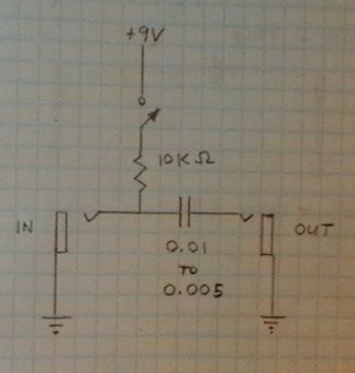
This schematic represents a cable TV signal booster amplifier circuit designed to enhance the signal strength of a cable TV system. It is recommended to use 75 Ohm coaxial cables for both the input and output connections, and the...
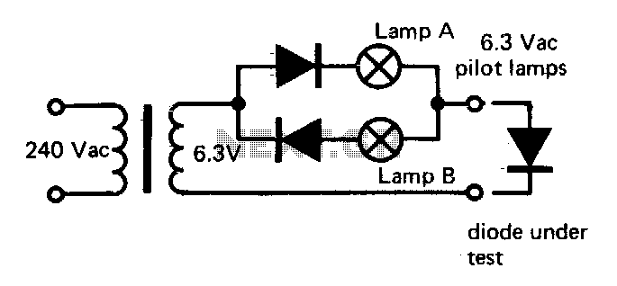
If lamp A or B is illuminated, the diode is functional. If both lamps are illuminated, the diode is short-circuited. If neither lamp lights up, the diode is an open circuit. The described circuit utilizes two indicator lamps, designated as...
Condenser microphones generally provide superior sound quality compared to dynamic microphones. For those unfamiliar with these two microphone types, a Wikipedia article can offer useful insights. Electret condenser microphones consist of two plates (capacitors), one of which vibrates in...
This circuit was developed to fulfill the requirement for a simple network tester that can be operated by a single individual. Previous commercial units necessitated the presence of a person at the other end to observe the remote LEDs,...
The following circuit illustrates the electronic diagram design for police and ambulance alarms. Features include simplicity and ease of assembly, as well as cost-effectiveness. This electronic schematic represents a basic alarm system intended for use in police and ambulance applications....

A balance indicator for a power supply that shows whether a symmetric power supply is truly symmetric. It utilizes two pairs of comparators from an LM339N quad comparator. The balance indicator circuit employs the LM339N quad comparator to assess the...