
Laptop Notebook Schematic

The laptop schematic circuit diagram serves as a critical resource for technicians involved in laptop repair. This diagram provides a comprehensive representation of the electronic components and their interconnections within the laptop. It typically includes details such as power supply lines, data buses, and signal pathways, which are essential for diagnosing and troubleshooting various hardware issues.
In addition to facilitating repairs, this schematic is particularly useful for tasks such as removing BIOS passwords. The BIOS (Basic Input/Output System) is fundamental to the operation of the laptop, controlling hardware initialization and providing runtime services for operating systems. When a BIOS password is set, it can prevent access to the system, making it necessary for technicians to understand the schematic in order to safely bypass or reset the password.
The circuit diagram may also include annotations on component values, pin configurations, and test points, providing further insight into the functionality of the system. Understanding these details enables technicians to perform repairs effectively, ensuring that components are replaced or repaired correctly. This knowledge is crucial for maintaining the integrity of the laptop's operation and performance, ultimately leading to successful repair outcomes.Laptop Schematic Circuit Diagram for Laptop Repair, Laptop Bios Password Remove. 🔗 External reference
Related Circuits
AC power is rectified and applied to the motor in one polarity when the momentary switch is held in one direction, and the polarity is reversed when the motor is held in the reverse direction. The remote car starter...
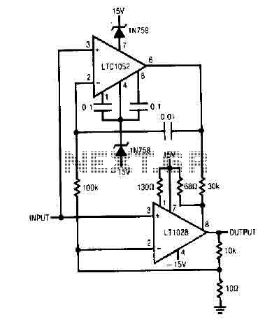
It uses the LT1052 and LT1028. The power supply should be dual with ±15V at 500mA. This is an ideal stabilized amplifier. The circuit utilizes the LT1052 and LT1028 operational amplifiers, which are known for their precision and stability. The...
Electronic circuits are presented in schematic form. A schematic is essentially a map that illustrates the path of current through various components. Each component is represented by a symbol, typically accompanied by a label or a value, or both....
This simple circuit employs a 741 operational amplifier (op-amp) in differential mode to function as a continuity tester. The voltage difference between the non-inverting and inverting inputs is amplified by the full open-loop gain of the op-amp. Initially, ignore...
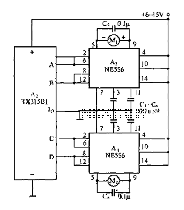
The travel remote control model is represented by a circuit diagram. The NE556 is a dual time base IC that includes two separate circuits, each consisting of a Schmitt trigger circuit. The output control is achieved through the TX315B1,...
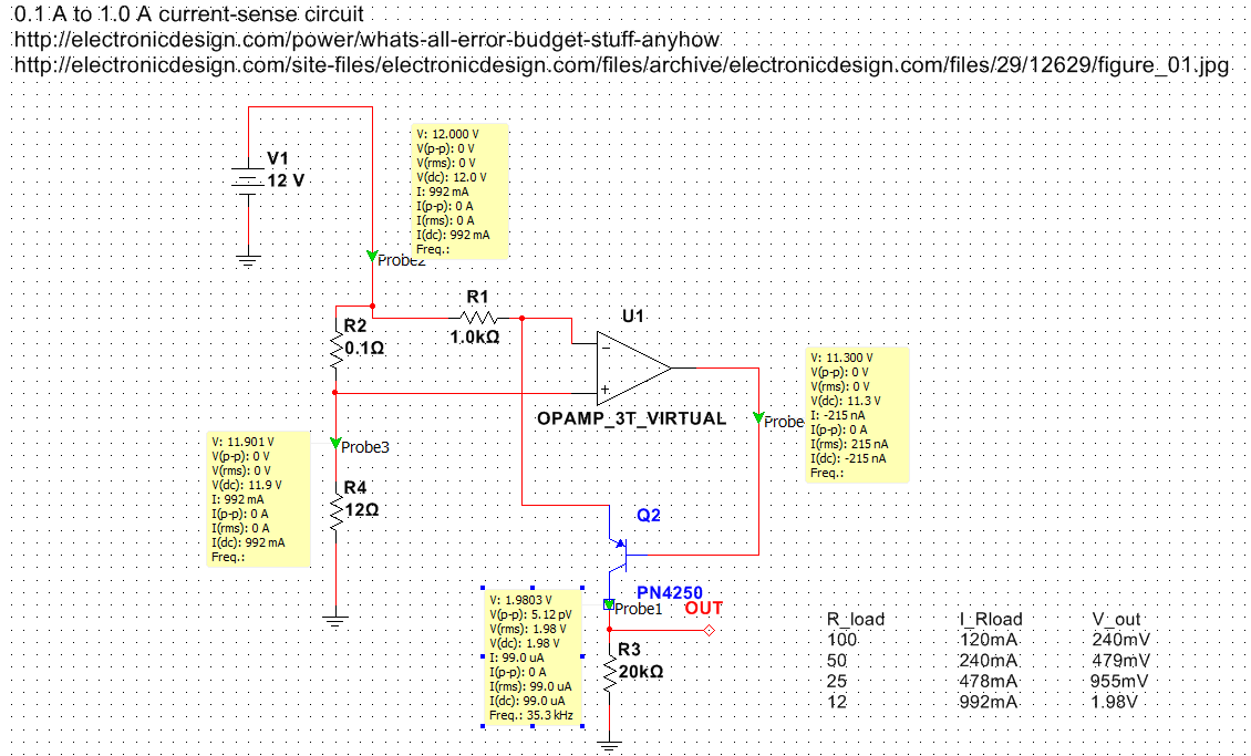
Exploring various methods for current sensing using standard operational amplifiers instead of specialized chips like the MAX4073T/F/H, which perform well but are relatively expensive. An article by Bob Pease discussing "error budgets" caught attention, particularly Figure Two of the...