
Current sense schematic question

The circuit for current sensing can be constructed using a standard operational amplifier configured in a non-inverting or inverting mode, depending on the specific requirements of the application. The operational amplifier will be connected to a shunt resistor placed in series with the load to measure the voltage drop across it, which is proportional to the current flowing through the circuit. The output voltage of the op-amp can be calibrated to provide a specific output voltage corresponding to the current, such as the 2 volts indicated in the referenced article.
For simulation purposes, the PN4250 transistor can be utilized to amplify the output signal from the operational amplifier, enhancing the sensitivity of the current sensing circuit. However, discrepancies in output voltage during simulations may indicate the need for further investigation into component values and configurations. The LM258 operational amplifier requires a sufficient power supply voltage to function correctly, particularly in configurations where the input signal approaches the positive supply voltage. Therefore, using a higher voltage supply, such as 14V, is advisable to ensure proper operation.
The Hall effect sensor presents an alternative for current sensing, particularly in applications where high current or alternating current is involved. Its cost-effectiveness and capability to handle a broader range of currents make it a viable option compared to traditional op-amps.
In the context of the solar-powered system, the current monitor PCB must be robust enough to handle the maximum expected current, necessitating the use of thicker copper traces on the PCB to minimize resistive losses and ensure thermal management. The design of the PDACs facilitates efficient power distribution across multiple LED fixtures, allowing for automated control based on environmental inputs, which is crucial for optimizing energy use in solar-powered applications.
The solar panel racks designed to allow manual adjustment for optimal sun exposure contribute to maximizing energy harvest while providing protection against adverse weather conditions. This thoughtful design approach enhances the reliability and efficiency of the solar power system, demonstrating the importance of integrating practical engineering solutions in renewable energy applications.Looking at different ways to do current sensing, using regular opamps, rather than dedicated chips like the MAX4073T/F/H, which work well, they are just rather expensive. So while poking around i found an article written by Bob Pease, , which talks about "error budgets" And the schematic fugure two, caught my eye As far i understood what Bob was talking about that curuit, should generate 2 volt on the output
if we have one amp through the shunt resistor, I decided to run the shcemati through an simulation tool or two to see whats up. In the one tool i tried where i had the PN4250 transistor, i consistently get around 6 volts on Vout, no matter what the current is.
I tried in LTspcie, and that just gives me 11. 2 volts (see attached model, i dont know if the lm258 and the 3906 suitable for this) If you add a +14v (or more) supply just for the LM258 the circuit will operate correctly, otherwise you need an op-amp which functions with inputs close to its +ve supply which are not common. JensAndree, the hall sensor is 3$ in small quantiites, so its a bout twice the price of the max4073m but i guess that the hall sensor might be better over larger current ranges and with AC.
looks very interesting, and i can see that you also found the mcp600x series opamp, i have found that that microchip has a lot of interesting analog parts. I am building a related system to yours, to power a server 24/7 using solar panel s and batteries, with a power brick as a backup.
The current monitor pcb you saw in the post is 1oz copper and is easily handling +/- 15A. I would like to test the board at the maximum ATO fuse rating of 40A when I get the time. I think I will have to up the pcb copper to at least 2oz for that much current. Good luck with your project. I do all of the lighting in my house with LED lights I designed and all 24 lights are 100% powered by the battery bank you saw in the post. I have attached a photo of the solar array that charges the battery bank ([8] 85W panels). Is this a 12 volt system, for the leds. In my original design i decided to go with 24 volts at the cable losses would be quite significant, or the cables would be unwieldy.
I must say that im pretty impressed with your solar panels. It almost looks like you have solar tracking on them. And you are using car fuses right mjlorton from South Africa, has been using those "automotive" fuses, and he has experienced that they melt, and dont blow. Take a look see Yes I do have a 12V system. I distribute the 12V from a distribution box via 10GA wire pairs fused at 10A. Each wire pair powers 4 LEDs lights max. The wire pairs go to circuit boards I call PDACs (Power Distribution and Control) mounted in 4" electrical boxes throughout the house.
The PDACs are all networked together and all are slaves controlled by one master PDAC. Touch switches and motion sensors are connected to the slave PDACs along with the LEDs. The master PDAC reads the motion sensors and touch switches via the network and then after executing control logic sends commands to turn the LEDs on and off also via the network. This allows the master controller to turn lights off automatically with no motion after a time delay.
a must for a solar powered system. The racks holding the solar panel are also my own design and allow for the panels to be rotated down for protection against hail or to be pointed at the sun by adjusting both azimuth and elevation. I have to move the panels manually but it only takes about 10 minutes to do all four racks. Thanks for the warning about the ATO fuses. I use only high quality name brand fuses but you can bet I will be contacting the manufacturer to follow up on this one.
Sometimes in spite of every effort to do the right thing with a design there can still be problems. Oh well! 🔗 External reference
Related Circuits
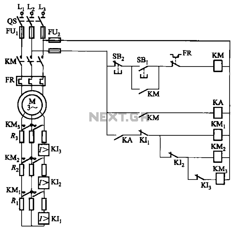
The circuit illustrated in Figure 3-161 features a first stage current detection mechanism utilizing a current relay (KI1) in series with a resistor (R1). The second stage employs another current relay (KI2) in series with a resistor (R2) for...
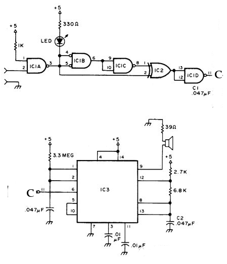
The NE556 timer can function as an indicator for the static state of a digital logic audible terminal. An audible logic probe is beneficial for visually inspecting a component while simultaneously checking the logic state at another point far...
The wide-range current pump for the precision phase-locked loop (PLL) circuit is a semi-precision circuit that provides an output current proportional to -V1, with a variation of approximately 10 to 15%, across a three-decade range. The 22 MΩ resistors...
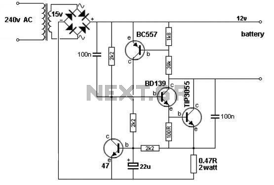
A simple 12V battery charger circuit can be designed using a TIP3055 power transistor to limit the current to the battery. The circuit turns off when the battery voltage reaches approximately 14V or if the current exceeds 2A. This...
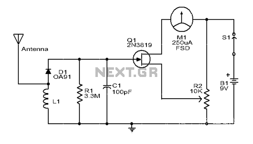
This is a simple and low-cost broadband high-frequency electric field strength meter. The field strength of the radio signal is converted into a DC measurement for analysis. The signal is captured by a coil and processed through a diode...
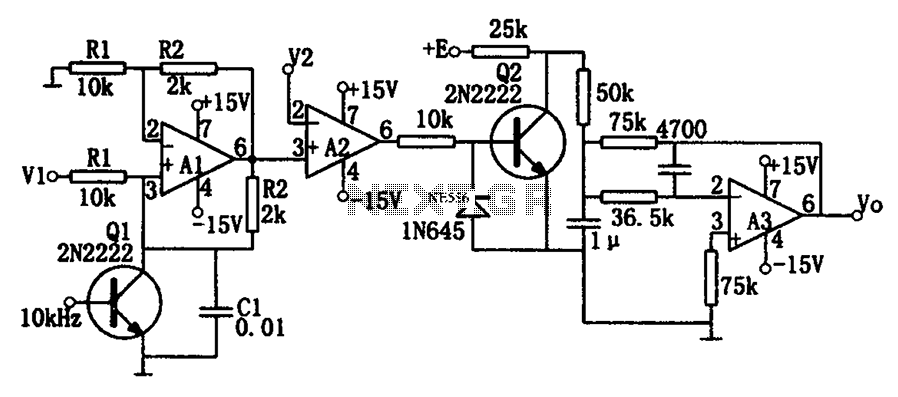
As illustrated in the dividing circuit diagram, A1 consists of a voltage-controlled current source, A2 functions as a voltage comparator, and A3 is configured as an active low-pass filter. When the time constant R1C1 is equal to the clock...