
Latching Continuity Checker

The circuit operates primarily as a continuity tester, designed to identify both short circuits and open circuits in electrical components or wiring. The core of the circuit consists of an R-S flip-flop formed by operational amplifiers U1A and U1B. The configuration allows for stable output states that indicate whether continuity exists in the circuit under test.
When switch S2 is toggled to the up position, the circuit enters a state where it checks for continuity. If a complete path exists, LED1 illuminates, signaling that continuity is present. This feature is essential for ensuring that connections are intact and functioning correctly.
The reset functionality is provided by switch SI, which, when activated, clears the flip-flop, ensuring that the tester can be reset before performing a new test. This is crucial for maintaining accurate readings and preventing false indications from previous tests.
In the down position, switch S2 allows the circuit to detect momentary interruptions in continuity. This mode is particularly useful for identifying intermittent faults that may not be present during a static test. When a break in continuity occurs, LED1 lights up, providing immediate visual feedback to the user.
Overall, this circuit is a practical tool for troubleshooting electrical systems, offering a straightforward method for detecting both persistent and transient faults in wiring and components. This circuit detects brief shorts or opens. When S2 is in the up position, the circuit indicates if there is or was continuity by lighting LED1. U1A and U1B are connected as an R-S flip-flop. SI resets the tester. When S2 is in the down position, a momentary interruption in continuity will light LED1. This tester is good for detecting intermittent shorts or opens.
Related Circuits
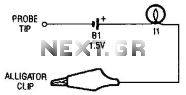
The continuity tester consists of a battery and a lamp connected in series, with one end of the circuit terminated with an alligator clip and the other end connected to the probe tip. The continuity tester is a fundamental...

A balanced Wheatstone bridge controls a JK flip-flop that utilizes an operational amplifier as an interface. This configuration subsequently drives a relay. Resistors R1 through R4 can be increased in value to enhance sensitivity. The circuit employs a balanced Wheatstone bridge,...
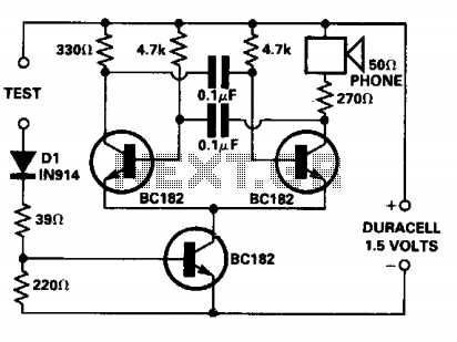
The continuity tester is designed for tracing wiring on printed circuit boards. It consumes significant power only when the test leads are shorted, eliminating the need for an On/Off switch. The voltage applied at the test terminals is not...
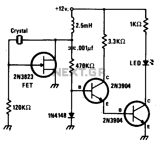
This circuit is a simple Pierce oscillator with an LED go/no-go display. The checker works best with crystals having fundamental frequencies in the seven to eight megahertz range. The Pierce oscillator circuit is a popular choice for generating high-frequency signals,...
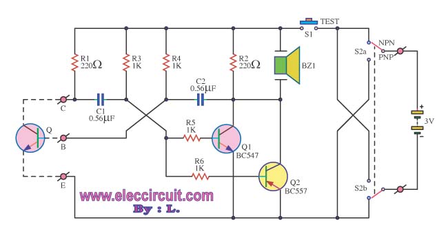
The transistor was checked by measuring the resistance between its various pins. Occasionally, issues arise when measuring the resistance between them. The process of measuring resistance in a transistor is an essential diagnostic technique used to evaluate its functionality. A...
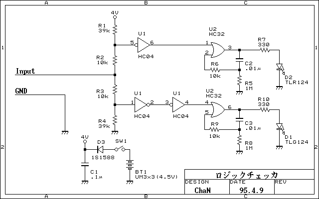
Simplified logic checker. Logic voltage levels have the ability to display LED. "H" in the LED is green, "L" and red LED lights, and so both the open and goes out. But not only that was put on the...