
Latest Car Alarm Simulator circuit

The car alarm simulator circuit is designed to provide a visual indication of the vehicle's operational status using an LED. The primary component of this circuit is a voltage comparator, which can be constructed using an operational amplifier (op-amp). The op-amp compares the voltage levels from two points: one connected to the vehicle's battery and the other connected to the alternator output.
When the vehicle is off, the voltage at the battery terminal is at a nominal level, typically around 12 volts. However, when the engine is started, the alternator generates a higher voltage, often between 13.5 to 14.5 volts, which is detected by the circuit. The op-amp is configured in a comparator mode, with one input connected to the battery voltage and the other to the alternator output.
In this configuration, when the alternator voltage exceeds the battery voltage, the output of the op-amp switches from low to high, activating the LED. This visual output serves as an indication that the vehicle is running. The circuit can be further enhanced by incorporating a resistor to limit current through the LED, ensuring that it operates within safe parameters.
Additional components may include a potentiometer for fine-tuning the voltage thresholds, allowing for precise adjustment based on specific vehicle characteristics. A small capacitor may also be added to smooth out any fluctuations in voltage readings, providing a stable output.
This car alarm simulator circuit can be assembled on a breadboard or designed into a printed circuit board (PCB) for a more permanent installation. It offers a practical solution for automotive enthusiasts looking to monitor their vehicle's operational status with a simple yet effective indicator.This is a car alarm simulator which using the LED as a simulation output. This simple circuit can tell you whether your car is running or not by detecting the voltage difference when the car is on and off. This occurs because when your car is running the Alternator puts a out a voltage a little bit higher than when the car is off.
This circuit act ually is a kits, you can get the kits at But it is very possible to you to build your own car alarm simulator circuit. 🔗 External reference
Related Circuits

This is a simple basic design of a servo motor controller with a pulse generator. It utilizes the CMOS IC 7555 in astable mode to generate pulses for driving the motor. The servo motor controller circuit employs the CMOS IC...
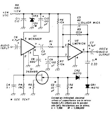
An audio signal applied to VI is passed through the operational amplifier 741, U2. After being amplified, the output signal V2 is sampled and applied to a negative voltage doubler/rectifier circuit composed of diodes CR1 and CR2, along with...
The circuit-delay relay for speakers serves as a delay mechanism that prevents the immediate activation of speakers when the amplifier is powered on. This feature is designed to protect the speakers from potential damage caused by sudden power surges....
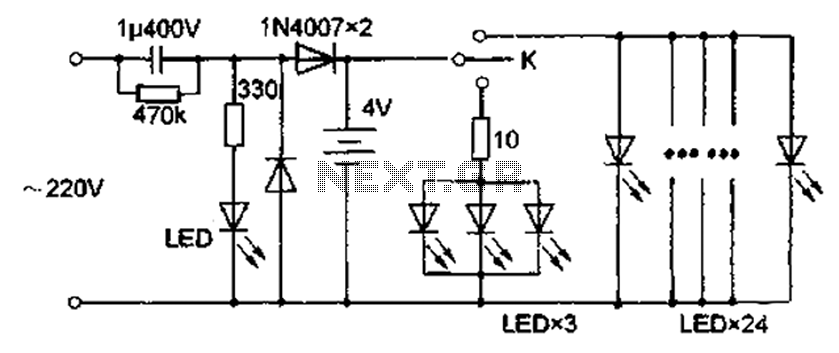
The circuit diagram depicted in Figure 5 illustrates a system for charging a lead-acid battery using 220V AC power. The circuit employs a capacitor, buck converter, and diode rectifier for this purpose. A red LED indicates the charging status....

A, B, and C are used for a high-power split-phase system. The A + B' C' arrangement serves as a phase line for a range generator. The A-A' indole path string includes two 220V / 15W bulbs, which are...
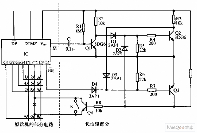
A simplified long-distance call lock is illustrated in the accompanying image. This device is designed to prevent long-distance calls while maintaining the original functionality of the phone. Although it consumes power, it exhibits excellent compatibility. When switch K is...