
Diode Tester schematic
The described circuit functions as a diode tester, utilizing a straightforward design to determine the operational status of various diodes. The circuit is powered by a 9 V battery, which provides the necessary voltage for testing.
The primary components include resistors, diodes, and transistors. Resistors R1 and R6, both rated at 1 kOhm, are likely used to limit current through the circuit, ensuring that the LED (D1) operates within safe parameters. R2, a 100 kOhm resistor, may serve as a pull-down or pull-up resistor, depending on its connection within the circuit, to stabilize the voltage levels when the switch is not engaged.
Resistors R3, R5, and R7, each rated at 22 kOhm, are likely used in conjunction with the transistors T1 and T2 (BC548) to control the switching mechanism of the tester. The BC548 transistors are NPN types, which are commonly used for switching and amplification purposes. They may be configured in a way to enhance the sensitivity of the tester, allowing for the detection of diode functionality through the LED indication.
R4, valued at 2.2 kOhm, likely serves a similar purpose as the other resistors, possibly providing additional current limiting or feedback within the circuit.
The LED (D1) acts as an indicator, illuminating when the diode under test (D2) is functioning correctly. The circuit may include a switch that allows users to select different test modes or conditions, as indicated by the table mentioned in the description. This switch configuration is essential for providing clear feedback on the state of the diode being tested.
In summary, this circuit is a practical tool for testing diodes, employing a combination of resistors, transistors, and an LED to provide visual feedback on the operational status of the diode. The design is efficient and straightforward, making it suitable for both educational purposes and practical applications in electronics troubleshooting.With this tester you can check whether a diode is working properly. In the table you can see what LED to indicate the positions of the switch and condition of the diode. The circuit can be connected to a 9 V battery. R1, R6 = 1 kOhm R2 = 100 kOhm R3, R5, R7 = 22 kOhm R4 = 2.2 kOhm D1 = LED D2 = Diode test T1, T2 = BC548 🔗 External reference
Related Circuits
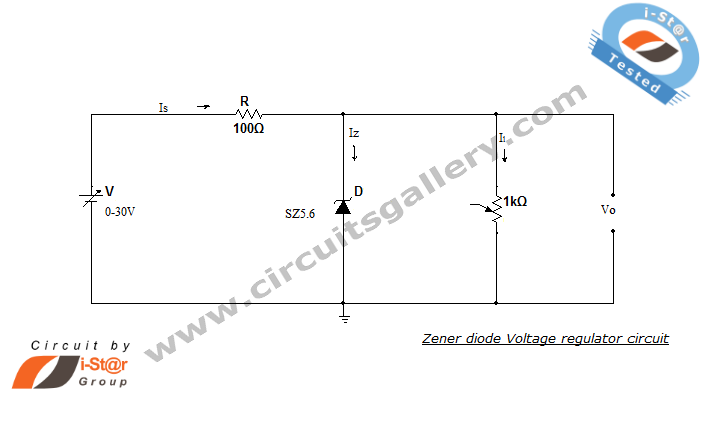
A Zener diode regulator is a fundamental electronic circuit valuable for hobbyists. This circuit provides a regulated output voltage, suitable for biasing other circuit components. The Zener diode operates in the reverse breakdown region, maintaining a nearly constant voltage...
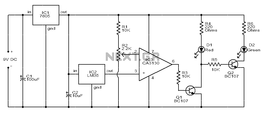
The circuit consists of two light-emitting diodes (D1 and D2) whose operation is controlled by the ambient temperature. A temperature sensor, the LM35, generates an output of 10 mV for each degree of temperature increase. A reference potentiometer, R2,...
It is well known that pests like rats, mice, etc. are repelled by ultrasonic frequency in the range of 30 kHz to 50 kHz. Human beings can't hear these high-frequency sounds. Unfortunately, all pests do not react at the...
This project involves a straightforward soil moisture detection circuit that utilizes only four components and operates with a 3-volt battery. The circuit is designed to identify the presence of moisture in the soil of any plant and activate an...
This infrared transmitter utilizes pulse width modulation (PWM). The transmitter is equipped with an LM567 tone decoder circuit. An audio signal (at least 50 mV peak-to-peak) is amplified with transistor T1 and subsequently used to modulate IC1. The frequency...
This is a straightforward tester designed to verify the fundamental operations of an infrared remote control unit. It is cost-effective and simple to assemble. The tester utilizes the infrared receiver module TSOP1738. The operation of the remote control is...