
LC Resonant Frequency Meter

The described circuit is an inductance measurement device designed to operate in the range of hundreds of microhenries to several millihenries. The core of the device is an oscillator built around the LM393 comparator, which is configured to oscillate at the resonant frequency of an LC parallel tuned circuit. The device is capable of operating at lower frequencies, with a tunable range from 100 kHz down to standard measurement frequencies like 1 kHz and 400 Hz. This flexibility allows for direct comparisons with results obtained from precision LRC bridges.
The oscillator circuit utilizes an LC tank circuit, which consists of the inductor under test and a reference capacitor. A dual-row connector facilitates easy connections to the components under test, allowing for a straightforward switch between measuring inductors and capacitors. This is achieved by soldering a reference inductor to one set of contacts while using the other for the capacitor under test.
The choice of components is critical for the performance of the circuit. The LM393 comparator is suitable for frequencies just above 100 kHz, while faster comparators like the LM311 can be utilized for higher frequency applications. The circuit layout is designed with careful consideration of component placement to minimize interference. The oscillator components are positioned on the opposite side of the board from the microcontroller (AT90S2313) and its associated crystal oscillator to prevent any potential coupling that could affect the oscillator's frequency stability.
The construction of the circuit on a phenolic board with one pad per hole ensures a robust and reliable prototype. The design prioritizes accessibility and ease of use, making it suitable for both home and laboratory settings. This inductance measurement device represents a practical solution for measuring inductance values accurately and efficiently across a range of applications.Recently, I have needed to measure inductances in the hundreds of microhenries to several millihenry range. Though I have a pretty good LRC meter and an excellent bridge on my workbench in Mesa, Arizona, I wanted to make these measurements in my home in Thailand, thus I decided to put something together.
The RF Inductance meter on this website is good for low value rf inductors, but because of the way it works - putting a sharp-edged square wave through the inductor -its not suitable for inductors made with high permeability ferrites (Because of pulse shape distortion that results from high frequency losses in the core.) This meter operates at lower frequencies, and by careful selection of the resonating capacitor, the oscillator can be made to run anywhere from 100 kHz on down. This makes it possible to test near standard frequencies like 1 kHz and 400 Hz, to compare results with precision bridges.
This is basically just an oscillator based on a comparitor and a frequency meter. The oscillator oscillates at the resonant frequency of an LC parallel tuned circuit. A really nice version of this was created by Chris Krah using an AT90S1200, including floating point math, etc. to display the L and C readings directly. I'll post a link to Chris' version once it is published on the web (it was posted on the AVRFreaks board).
The LM393 comparitor only seems to work accurately a little past 100 kHz, but it is good enough for my purposes. Faster comparitors like the LM311 can work well at higher frequencies. The second comparitor in the package was left floating. A dual-row connector is used to connect the resonant circuit under test to the oscillator. It has two rows so there will be one pair of contacts for the reference capacitor, and a second pair of contacts to connect for inductor under test.
Or, if one wants to measure capacitors, a reference inductor can be soldered to the connector and the other set of contacts used for the capacitor under test. I built this on a phenolic board with one pad per hole. As shown in the photograph above, the board is laid out pretty much the same as the circuit diagram. I made sure the oscillator components were on the opposite side of the LM393 from the AT90S2313 and its crystal oscillator to minimize coupling as a precaution because I was concerned that energy from the AT90S2313 oscillator could cause affect the frequency of the LM393 oscillator.
🔗 External reference
Related Circuits
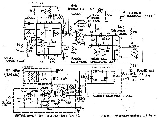
A deviation monitor can be constructed by connecting a frequency modulation (FM) detector to an AC voltmeter, calibrating the meter in units of frequency deviation. One method for detecting or demodulating the FM signal is via a phase-locked loop...
Figures (a) and (b) illustrate two basic oscillator circuits operating at 2 MHz. The circuit design allows for adjustment of the optimal operating point through testing. The two oscillator circuits depicted in the figures utilize different configurations to achieve stable...
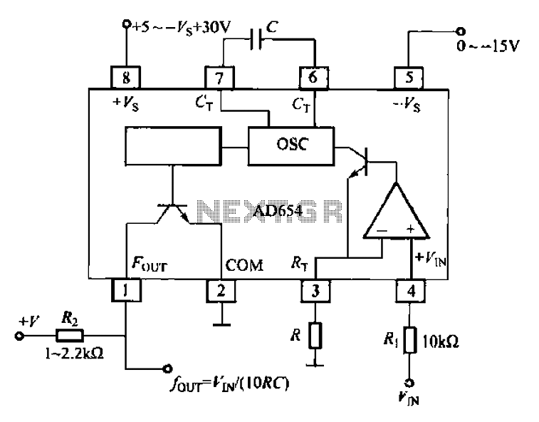
The AD654 voltage-frequency converter is a low-cost device that operates with a single supply voltage ranging from +5V to +36V, as well as with dual supplies of +5V to +18V. It can handle a maximum input voltage of 36V...
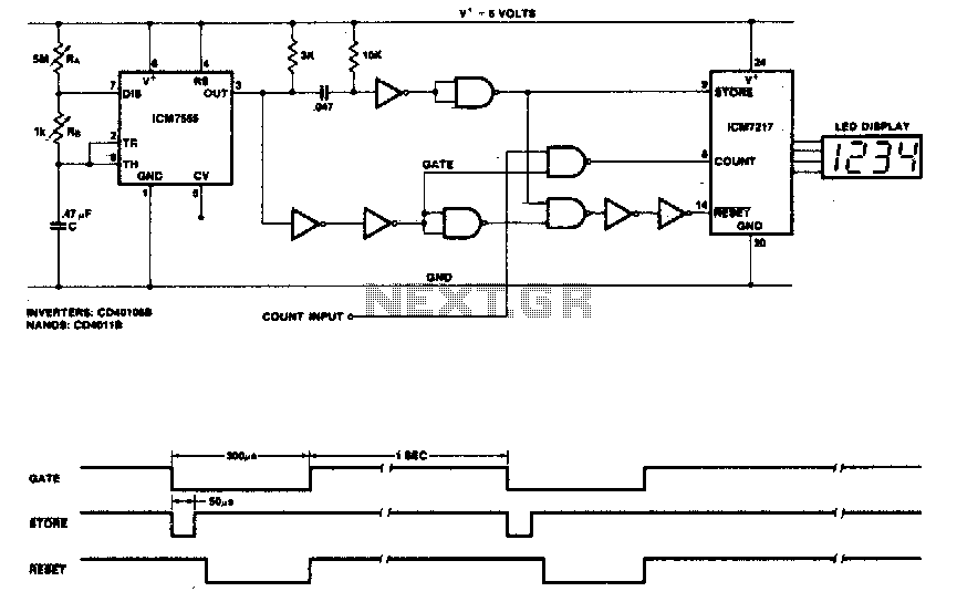
This circuit utilizes the low-power ICM7555 (CMOS 555) to generate the gating, STORE, and RESET signals. The timer is configured as an astable multivibrator to provide the gating signal. Calibration of the system is achieved using a 5 MΩ...
An alternating display for a version 1 nixie clock inspired new logic designs for switching signals to the display. The design eliminated the 4013 flip-flop and two 4017 counters, leading to a redesign of the hours section and reset...
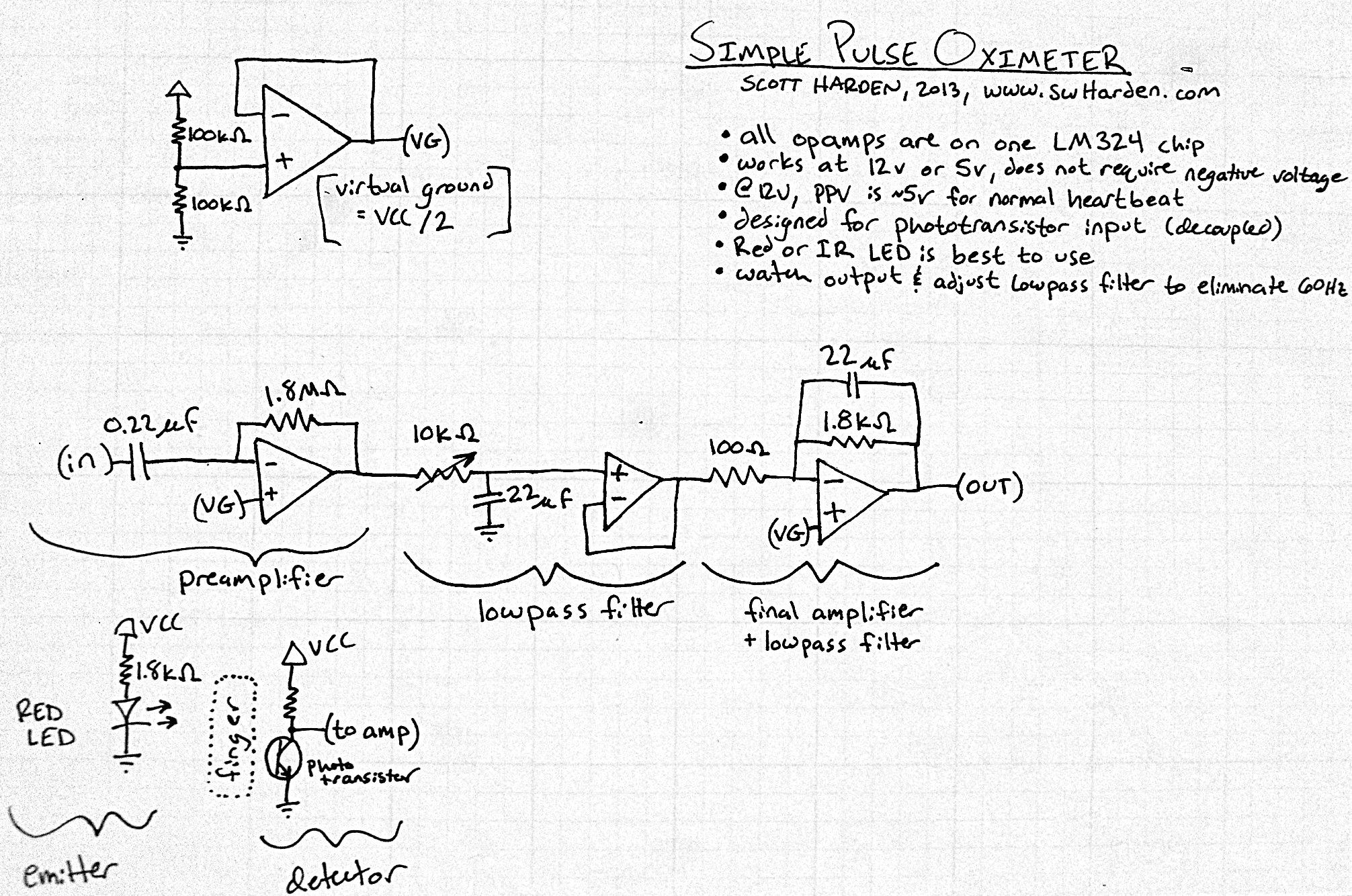
The input capacitor for the phototransistor at the bottom is responsible for feeding the operational amplifier (op-amp). However, the output from the phototransistor consistently remains between ground (GND) and the supply voltage (Vcc). The necessity for an input capacitor...