
LC189 making decorative lanterns with fans

The decorative light circuit for fans operates by integrating various electronic components to achieve a visually appealing lighting effect synchronized with fan speed. The step-down rectifier circuit converts the AC input voltage to a lower DC voltage suitable for the operation of the LC189. This integrated circuit is essential for controlling the timing and intensity of the LEDs based on the voltage applied to the inductor, which directly influences the fan's operational speed.
The fan speed control switch, utilizing resistors R1 to R3, allows for user selection of three different speed settings. Each setting modifies the input voltage to the LC189, thereby altering the flashing frequency of the LEDs. Capacitor C1 plays a crucial role in stabilizing the voltage at pin 8 of the LC189, ensuring reliable performance.
The oscillation circuit formed by R4 and C2 is responsible for generating the necessary timing signals that drive the LED patterns. The varying amplitude of the input signal directly affects the output waveform frequency, which is critical for achieving the desired lighting effects. The outputs A to D connect to a 4x4 dot matrix configuration, where each LED is strategically placed to create dynamic visual displays.
The current-limiting resistors R6 to R9 are designed to protect the LEDs and the arc tube from excessive current, which could lead to damage. The choice of resistance values is dependent on the power supply voltage; thus, it is vital to select the appropriate resistor values to ensure the longevity and functionality of the circuit. This careful design consideration allows for a versatile and visually captivating decorative light circuit that enhances the ambiance of any space.Fans decorative light circuit in Figure 2-130, the circuit consists of step-down rectifier circuit, lattice specific integrated sound and light control roads and other componen ts. Core device circuit is LC189. This decorative lamp is the use of different voltage amplitude on the inductor fan speed, forcing LC189 control different LED flash frequency, voltage, high frequency fast flash, slow and vice versa. Resistance Rl ~ R3 connected on three-block fan speed control switch, the capacitor C1 is coupled to the input of LCI89 8 feet.
R4 and C2 are manifold outer contact oscillation RC components. Circuit output waveform frequency because the amplitude of the input signal varies, the output of A ~ D row and column output terminal f ~ r connected to 4x4 dot matrix, between the light emitting diode LED1 ~ 16 connected row line and column line, arc tube to press on section Figure 2-127 shows the level change and shiny, which can be formed is wonderful visual effects. Resistor R6 ~ R9 current limiting resistor of the arc tube, which along with the power supply voltage level may be, the machine uses 6V DC power supply, it is appropriate resistance 120 Q, if the power supply voltage of 12V, current limiting resistor should be increased to 390Q.
Related Circuits
Discrete blinking LEDs are convenient, but the blink rate and duration are not configurable. Experimentation with transistors, resistors, and capacitors was attempted to modify the blinking LED behavior. Ultimately, the abundance of additional electronic components led to the conclusion...
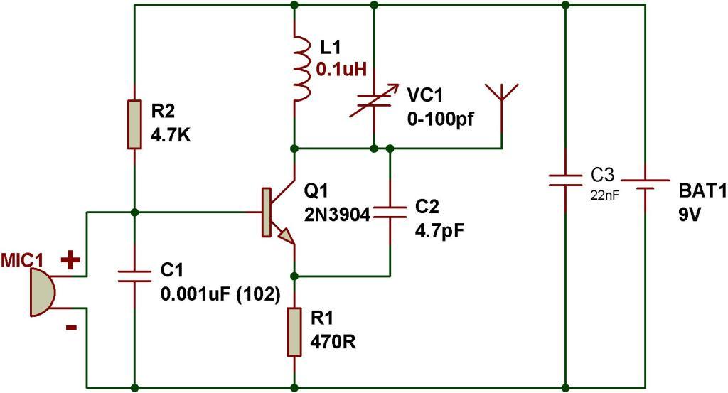
This tutorial outlines the construction of a simple FM transmitter utilizing a single transistor. The project requires minimal components, making it suitable for beginners. Before proceeding, refer to the schematic provided below, which details the components necessary for building...
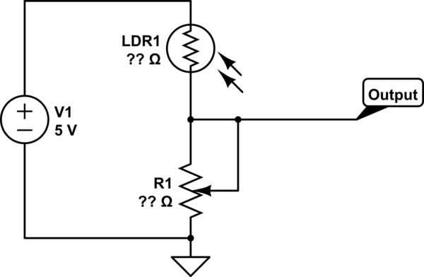
This part of the circuit is isolated from any other component, except for the 5V and ground connections. It includes LEDs and a shift register, which may not interact significantly. The LDR (Light Dependent Resistor) is utilized solely as...
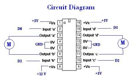
A remote Sun SPOT will transmit data to a Sun SPOT mounted on a car, which will control an integrated circuit (IC) according to the digital input/output pins D0 to D3. The IC will subsequently drive the motors that...
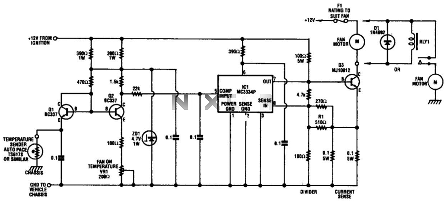
The circuit is based on a commercial temperature sensor (TS6178) and an MC3334P ignition chip. When the radiator temperature increases, the sensor pulls the base of Q2 low via Q1, which is wired as a diode. Q2's collector thus...
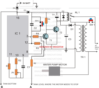
The following multi-function water level controller circuit is based on suggestions made by Mr. Usman. This circuit includes several requested modifications and detailed specifications. 1) To protect the motor from potential overheating as a safety feature, an automatic shutdown...