
potentiometer Making an adjustable resistance

The circuit under discussion features a Light Dependent Resistor (LDR), which is a crucial component for sensing light levels in various applications. The LDR's resistance decreases as the light intensity increases, allowing it to effectively measure ambient light conditions. In this specific circuit, the LDR is connected to a microcontroller or a shift register, which processes the analog signal received from the LDR.
The shift register serves as an interface to convert the analog signal from the LDR into a digital format that can be understood by the microcontroller. This conversion is essential for further processing and decision-making based on the light levels detected by the LDR. The inclusion of LEDs in the circuit may serve as indicators to visually represent the state of the LDR or the output of the shift register, providing feedback to the user.
The isolation of this circuit from other components, aside from the power supply (5V and ground), ensures that it operates independently, minimizing interference from other parts of the system. This design choice is particularly beneficial in applications where precise light measurement is critical, such as in automatic lighting systems or ambient light sensors in smart devices.
In summary, the LDR's primary role is to monitor ambient light levels, while the shift register and LEDs enhance the circuit's functionality by enabling digital processing and visual feedback, respectively. The overall design emphasizes clarity and effectiveness in light sensing applications, ensuring reliable operation within the specified parameters.Actually this part of the circuit is isolated from any other component (except via 5v & ground). Other than that, you can find LEDs and a shift register, but I guess they do not interact much. Or do they The ldr is used only as a light sensor. is there more to it Antoine_935 Apr 26 `13 at 23:28 I mean, what is the LDR`s purpose Are you se nsing ambient light level Are you changing the light level applied to the LDR with an LED to get a voltage-controlled resistor Is it just there to decorate the diagram XMPPwocky Apr 26 `13 at 23:30 🔗 External reference
Related Circuits
This regulated power supply is adjustable between a few volts and 15V using P1, while P2 is used to set the upper limit at 15.0V. The value of R6 is calculated as 0.7V divided by Imax, where Imax represents...
Using a modern multimeter to measure current can sometimes be difficult. Many of these meters will only measure up to one amp. However, many 112-volt DC powered projects draw a lot more than that. If you have ever thought...
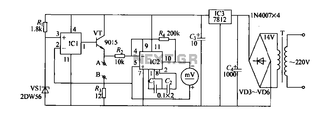
The contact resistance measuring circuit is illustrated in the figure. It primarily consists of a constant current circuit and an amplifying circuit. Operational amplifier IC1 is configured as a voltage follower, and the voltage across the load equates to...
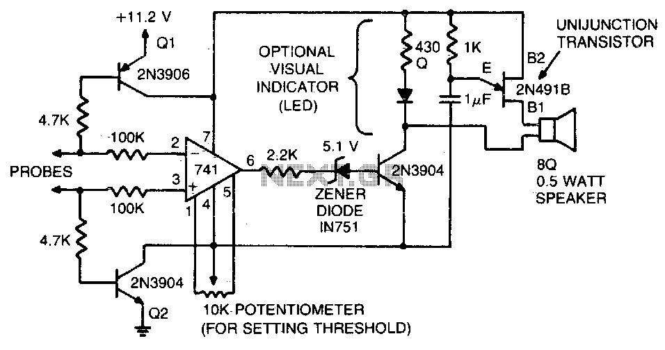
This tester is designed to verify integrated circuit (IC) printed circuit boards. It incorporates two 4 kΩ resistors along with transistors that inhibit current flow through the operational amplifier until the probe circuit is fully established. Additionally, a zener...
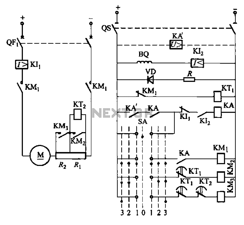
The circuit depicted in Figure 3-190 includes an armature circuit with two startup resistors, Ri and Rz, connected in series through the main switch SA to facilitate starting, stopping, and speed control. During the startup phase, two relays, KTi...
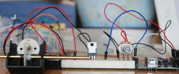
A quick circuit showing how to control the speed of a DC motor with a potentiometer with your Arduino board. Also shows how to use a TIP120 transistor to allow the Arduino control a larger power supply. This circuit utilizes...