
Thermostat Switch For Automotive Electric Fans Circuit

The described circuit utilizes the TS6178 temperature sensor to monitor the radiator temperature. As the temperature rises beyond a predetermined threshold, the TS6178 outputs a low signal, which is directed to the base of transistor Q2 through Q1, configured as a diode for signal conditioning. This configuration ensures that Q2 operates in a switching mode.
When the base of Q2 receives a low signal, it allows current to flow from its collector to its emitter, effectively turning Q2 on. As a result, the collector voltage of Q2 rises, which serves as a trigger for the ignition chip MC3334P (IC1). The MC3334P is designed to respond to this high signal at pin 7, activating its output to drive the fan motor through transistor Q3.
Transistor Q3 acts as a power switch for the fan motor, allowing it to be turned on or off based on the signal received from IC1. This configuration ensures that the fan operates only when necessary, thereby enhancing the efficiency of the cooling system. The circuit is designed for reliability and responsiveness, providing an effective solution for maintaining optimal radiator temperatures in automotive or industrial applications.
In summary, this circuit effectively integrates a temperature sensing mechanism with an ignition control strategy to manage the operation of a fan motor in response to temperature changes, ensuring efficient thermal management. The circuit, is based on a commercial temperature sensor (TS6178) and an MC3334P ignition chip, When the radiator temperature increases, the sensor pulls the base of Q2 low via Ql, which is wired as a diode. Q2`s collector thus goes high and triggers IC1, which switches its pin 7 output high and turns on the fan motor via Q3.
Related Circuits
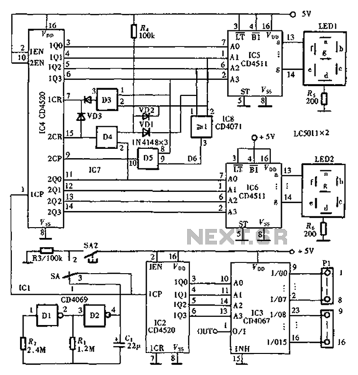
An automatic inspection circuit designed for the simultaneous detection and control of multiple production equipment. This inspection circuit can perform sixteen regular inspections of production equipment. It consists of a pulse generator, multiple inspection circuits, and an automatic inspection...
This system is designed to communicate or transmit a text message from one location to another using a wireless circuit. The text message is encrypted with a microcontroller, and the encrypted message is transmitted wirelessly. At the receiving end,...

The following circuit illustrates the electrical circuit diagram for the Honda CB750 motorcycle. Features include a turn signal relay, oil pressure switch, and neutral switch. The Honda CB750 electrical circuit diagram is designed to facilitate the understanding and troubleshooting of...
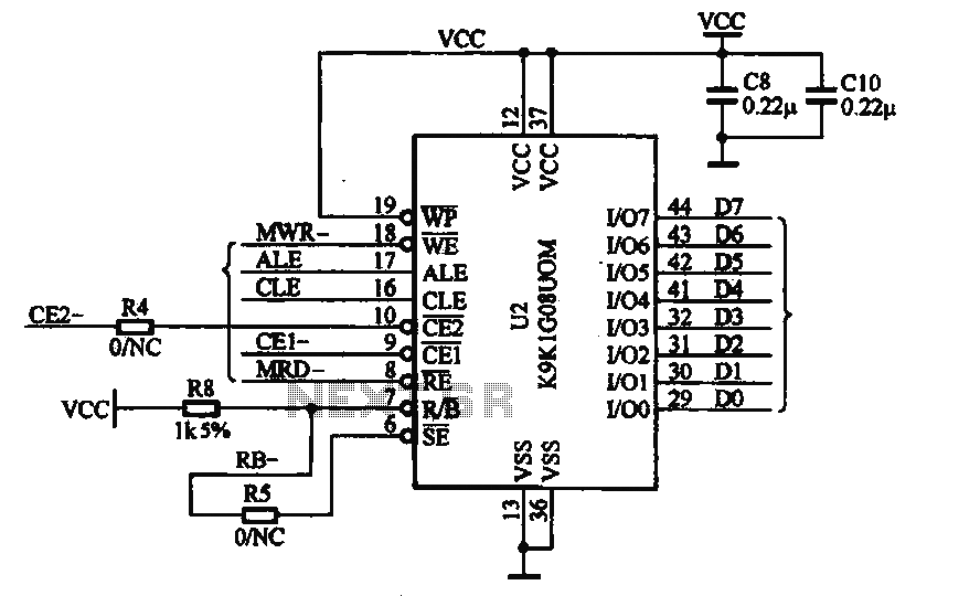
This document illustrates the application of the MP3 player memory chip ACU7505 within a clamor circuit, designed to support the overall machine CPU and MP3 decoder core. The chip is utilized to address high data storage capacity requirements, implemented...
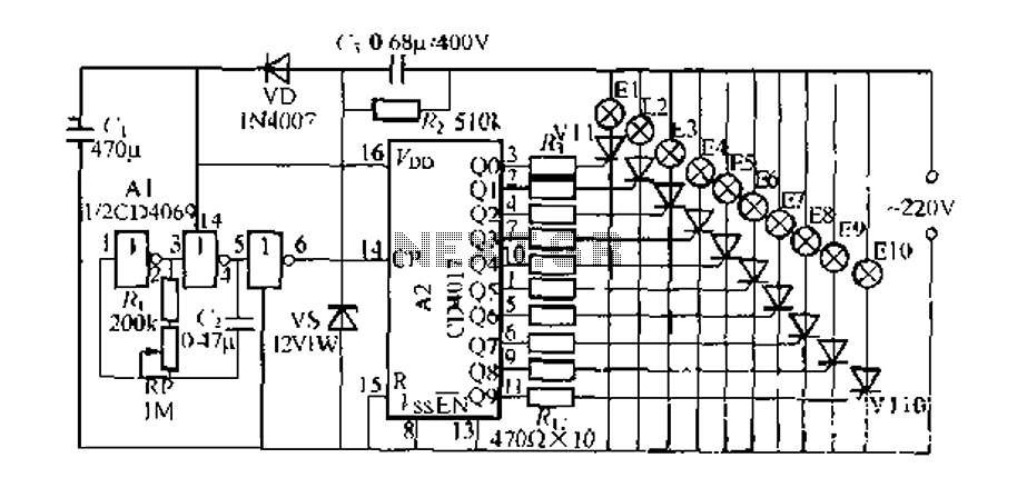
The digital integrated circuit consists of a controller for a string of ten road flashing lights, which drives the El-El0 string lights in a flashing cycle. The system utilizes a ten-count decoder, specifically the CD4017 digital integrated circuit. When...

Audio power amplifier circuit utilizing the LA4112 integrated power amplifier along with additional components as shown in the figure. The audio power amplifier circuit based on the LA4112 integrated power amplifier is designed to deliver high-quality audio amplification for various...