
Ship Navigation lights circuit

The circuit operates as a self-oscillating multivibrator, where transistors VTi and VT2 are configured to create a feedback loop that continuously switches the states of the transistors. This oscillation generates a square wave output that is used to trigger the thyristor (VT3). The thyristor, once triggered, allows current to flow through the connected load, which consists of the flashing lights.
The adjustment potentiometer (RP) plays a crucial role in determining the frequency of oscillation. By varying the resistance of RP, the time constants of the charging and discharging cycles of the capacitors in the circuit are altered, thus changing the frequency of the output signal. This adjustment directly affects the flashing rates of the lights. The Hi (red), Hz (green), and Ha (yellow) lights are connected in such a way that their flashing cycles correspond to the frequency set by the potentiometer.
The design allows for visual feedback through the colored lights, providing a clear indication of the operational state of the circuit. The use of different colors for the lights also facilitates easy identification of the flashing patterns, making it user-friendly for applications that require visual signaling. Overall, this multivibrator circuit is a practical implementation for creating variable flashing light signals using simple electronic components. By the transistor VTi, VT2 composition self-excited multivibrator output signal VT3 put large after a thyristor trigger pulse. Adjustment potentiometer RP, can change the oscil lation frequency, thereby adjusting the flashing lights Hi (red), Hz (green), Ha (yellow) flash cycle.
Related Circuits

This circuit diagram of a digital clock utilizes six common anode seven-segment displays to indicate the time. It does not require microcontrollers or PICs for operation. The circuit operates using the MM5314 integrated circuit, functioning at either 50 Hz...
This document presents the circuit diagram of an IC-controlled emergency light with a charger, which functions as a 12V to 220V AC inverter circuit. The primary features of this circuit include automatic activation of the light during mains failure...

The SH-805 circuit serves as a holiday lights controller, as illustrated in Figure 2-64. It is similar to the SH-804 circuit board, although the pin locations and control functions differ. By pressing the SB button, users can select between...

A series of LEDs is used to alert the gardener when plants require watering. By utilizing two conventional digital integrated LEDs along with a series of additional LEDs, this device serves as a practical tool for gardening. It detects...

A preamplifier that operates on a single supply and is suitable for high-impedance crystal pickups is presented here. The circuit functions as a non-inverting AC amplifier, with the gain determined by the feedback resistor R4; a smaller R4 results...
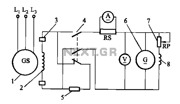
Adjust the exciter field rheostat RP to change the exciter output voltage, which in turn adjusts the generator excitation current, allowing for modifications to the generator output voltage for various purposes. The exciter field rheostat (RP) is a critical...