
LCD Module in 4-bit Mode
In designing circuits that incorporate the HD44780-based LCDs, careful consideration of the data lines is crucial, especially when operating in 4-bit mode. The four lower data lines (D0-D3) should not be left floating, as this can lead to unpredictable behavior and potential damage to the display. Instead, employing pull-down resistors connected to GND ensures that these lines are held at a defined logic level, thereby preventing them from floating. This configuration enhances the reliability of the system, particularly during the initialization phase when the display may inadvertently enter an undefined state.
When connecting the display to a microcontroller, it is essential to configure the R/W line appropriately. If the R/W line is tied to GND, the display is set to read mode, allowing data to be sent from the microcontroller without expecting any data back from the display. In scenarios where the R/W line is controlled by the microcontroller, the initialization sequence must be followed meticulously to ensure that the display is set to the desired mode of operation.
In practical applications, the use of a switch to disable the display can be beneficial, but it is imperative to ensure that this switch is not overlooked during testing. The microcontroller's firmware should also incorporate checks to manage the state of the display and the associated control lines effectively.
Overall, when designing circuits with HD44780-based LCDs, attention to the configuration of unused data lines and proper initialization procedures will lead to more robust and reliable electronic systems.In many projects use is made of alphanumeric LCDs that are driven internally by Hitachi`s industry-standard HD44780 controller. These displays can be driven either in 4-bit or 8-bit mode. In the first case only the high nibble (D4 to D7) of the display`s data bus is used. The four unused connections still deserve some closer attention. The data li nes can be used as either inputs or outputs for the display. It is well known that an unloaded output isne, but that a‚oating high-impedance input can cause problems. So what should you do with the four unused data lines when the display is used in 4-bit mode This question arose when a circuit was submitted to us where D0-D3 where tied directly to GND (the same applies if it was to +5 V) to stop the problem of‚oating inputs.
The LCD module was driven directly by a microcontroller, which was on a development board for testing various programs and I/O functions. There was a switch present for turning off the enable of the display when it wasn`t being used, but this could be forgotten during some experiments.
When the R/Wline of the display is permanently tied to GND (data only goes from the microcontroller to the display) then the remaining lines can safely be connected to the supply (+ve or GND). In this application however, the R/Wline was also controlled by the microcontroller. When the display is initialised correctly then nothing much should go wrong. The data sheet for the HD44780 is not very clear as to what happens with the low nibble during initialisation.
After the power-on reset the display will always be in 8-bit mode. A simple experiment (see the accompanying circuit) reveals that it is safer to use pull-down resistors to GND for the four low data lines. The data lines of the display are congured as outputs in this circuit (R/Wis high) and the enable` is toggled (which can still happen, even though it is not the intention to communicate with the display).
Note that in practice the RS line will also be driven by an I/O pin, and in our circuit the R/W line as well. All data lines become high and it`s not certain if (and if so, for how long) the display can survive with four shorted data lines.
The moral of the story is: in 4-bit mode you should always tie D0-D3 via resistors to ground or positive. 🔗 External reference
Related Circuits
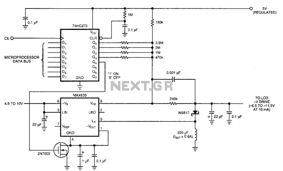
Laptop computers frequently utilize large-screen LCDs that require both a variable and a negative supply to achieve maximum contrast. This circuit operates from the system's positive battery supply and generates a digitally variable negative voltage to drive the display....
The circuit is designed for individuals who spend extensive hours exploring the various resources of this site. Although it comprises only three components, it effectively indicates whether the telephone line has been released after a prolonged connection via modem...
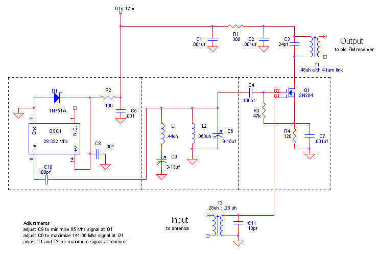
Here is my design for a modern receiving converter for pre-war FM sets. Accordingly, this article presents a design for listening to present day FM stations on a prewar FM set based on a MOSFET transistor and a TTL...
Here's PLL FM transmitter circuit from china. This circuit uses the familiar 2SC1971 for final power amplifier stage. The PLL controller of the FM transmitter use SAA1057 and PIC16F628 (download HEX file). More: If want to change the active...
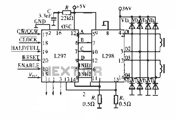
The circuit operates using a dedicated stepping motor controller, the L297. Pin 17 (CW/CCW) is utilized to control the rotation direction of the stepper motor. Pin 18 (CLOCK) regulates the speed of the stepper motor, while pin 19 (HALF/FULL)...
The circuit is drawn for measurement of acceleration from 1000 mg until + 1000 mg. It can be placed in the car and be supplied from the sheath of the electric lighter. The circuit includes one indicative LED and...