
LED Blinker with HT-2014M

The LED flasher circuit is designed to provide a visual indication through intermittent illumination of an LED. It utilizes the HT-2014 series of integrated circuits, specifically the HT-2014L and HT-2014M models, to achieve different flashing rates.
The circuit typically consists of the following components: a power supply, an LED, a resistor, a capacitor, and the HT-2014 integrated circuit. The power supply can be a standard DC source, such as a battery, providing the necessary voltage for the circuit operation.
In the HT-2014L configuration, the circuit is designed to produce a flash rate of approximately one flash per second. This is achieved by setting the timing components, namely the resistor and capacitor, to establish a time constant that dictates the on-off cycle of the LED. The HT-2014L operates by charging the capacitor through the resistor until a threshold voltage is reached, at which point the output transitions, turning the LED on. The capacitor then discharges, and the cycle repeats.
For the HT-2014M variant, the circuit is configured to double the flashing rate to approximately two flashes per second. This is accomplished by altering the values of the timing components or by using a different timing configuration within the integrated circuit, which reduces the time constant and thus increases the frequency of the flashing.
The LED is connected in series with a current-limiting resistor to prevent excessive current from flowing through it, which could cause damage. The choice of resistor value is critical to ensure that the LED operates within its specified current range, thereby providing optimal brightness without compromising longevity.
Overall, the simplicity of the LED flasher circuit makes it an excellent project for beginners in electronics, while also serving practical applications in visual signaling and decorative lighting.A very simple LED flasher circuit. With HT-2014L the circuit produces 1 flash per second and the HT-2014M produces 2 flashes per second. 🔗 External reference
Related Circuits
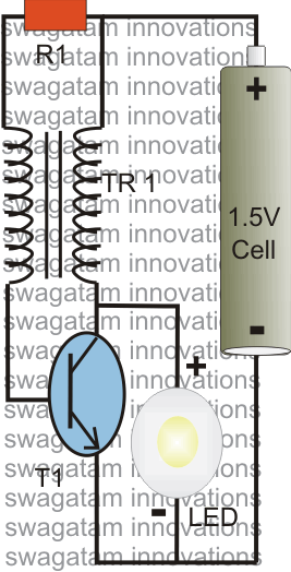
The post explains a simple 1 watt LED driver circuit using a single 1.5 V penlight cell through the joule thief concept. The coil may be wound over a T13 toroidal ferrite core using 0.2 mm or 0.3 mm...
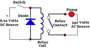
A relay is an isolated switch, with no direct connection between the switching device and the load. Relays are commonly used to control high-voltage devices, protecting sensitive low-voltage components from damage. Various types of relays exist, but electromechanical relays...
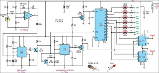
This circuit can switch two or more devices on and off in response to a series of rapid handclaps. The claps are picked up by an electret microphone. The circuit operates by utilizing an electret microphone, which serves as the...
The Automatic Forklift System (AFS) is engineered to enhance the safety and efficiency of warehouse stocking processes. Traditional manually operated forklifts pose injury risks to employees. The Automatic Forklift System (AFS) aims to mitigate these hazards. The Automatic Forklift System...
This unique hat is a product of a procrastination project. During the study break for final exams, an invitation was received for a friend's hat-themed birthday party. With little else to occupy time (aside from studying), the decision was...
This project takes advantage from -HOLD input, which is connected to push-button P1. As long as the -HOLD input is low, truth table's timeouts have no effect because this input serves to disable any state change provoked by timers....