
LED Color Fade Effect circuit diagram

This LED color fade circuit is designed to provide a visually appealing light effect through gradual intensity changes. The fading effect is achieved by utilizing a timing capacitor (30 µF) in conjunction with a resistor (100 kΩ) that determines the charge and discharge rate of the capacitor. By replacing the fixed resistor with a linear potentiometer, the user can customize the fading speed, making the circuit versatile for various applications.
The LM324 operational amplifier serves as the core of the circuit, where two of its four op-amps are configured to create the necessary control signals for the fading effect. The op-amps are set up in a feedback configuration that allows for smooth transitions in voltage levels, which in turn modulates the current flowing through the LED. The BC547 transistor acts as a switch, controlling the LED's on/off state based on the output from the op-amps.
The ultra-bright red LED, paired with a 220 Ω current-limiting resistor, ensures that the LED operates within safe parameters while achieving high brightness. The resistor is critical in preventing excess current that could damage the LED.
This circuit is suitable for decorative lighting, indicators, or any application where a gradual change in light intensity is desired. The design is simple yet effective, making it accessible for hobbyists and professionals alike.This is the circuit of LED color fade effect. Just like the name of the circuit, the light intensity of LEDs in this circuit will fade from high intensity to low intensity and then off. 30 uF condensator and the resistor marked with blue 100k control the speed of the fading. You can replace the 100 kilo ohm resistor with 100k linear potentiometer so you can adjust the speed any time. LM324 is an OP-Ampamplifier. There 4 op amp, and we just use 2 op amp in abovecircuit diagram. You may use the other 2 op-amp to build another similar circuit. Transistor is BC547 and the led isultra brightred with 220 ohm resistor in series. We aim to transmit more information by carrying articles. Please send us an E-mail to wanghuali@hqew. net within 15 days if we are involved in the problems of article content, copyright or other problems. We will delete it soon. 🔗 External reference
Related Circuits
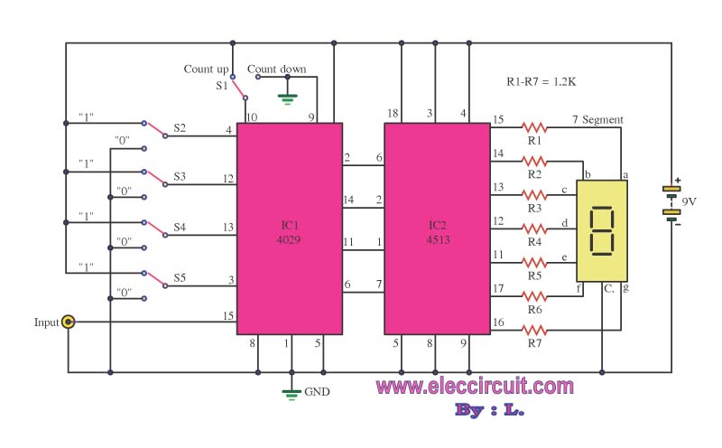
This is a simple digital counter circuit utilizing the IC 4029 to process binary data, which is then sent to the IC 4513, a driver IC for a 7-segment display to show the output. The digital counter circuit is designed...
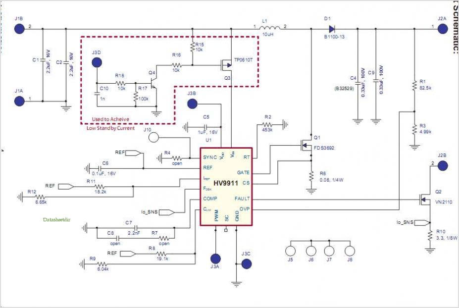
The BQ2000 is a programmable, monolithic integrated circuit designed for fast-charge management of nickel cadmium (NiCd), nickel metal-hydride (NiMH), or lithium-ion (Li-Ion) batteries in single or multi-chemistry applications. The BQ2000 detects the battery chemistry and employs optimal charging and...
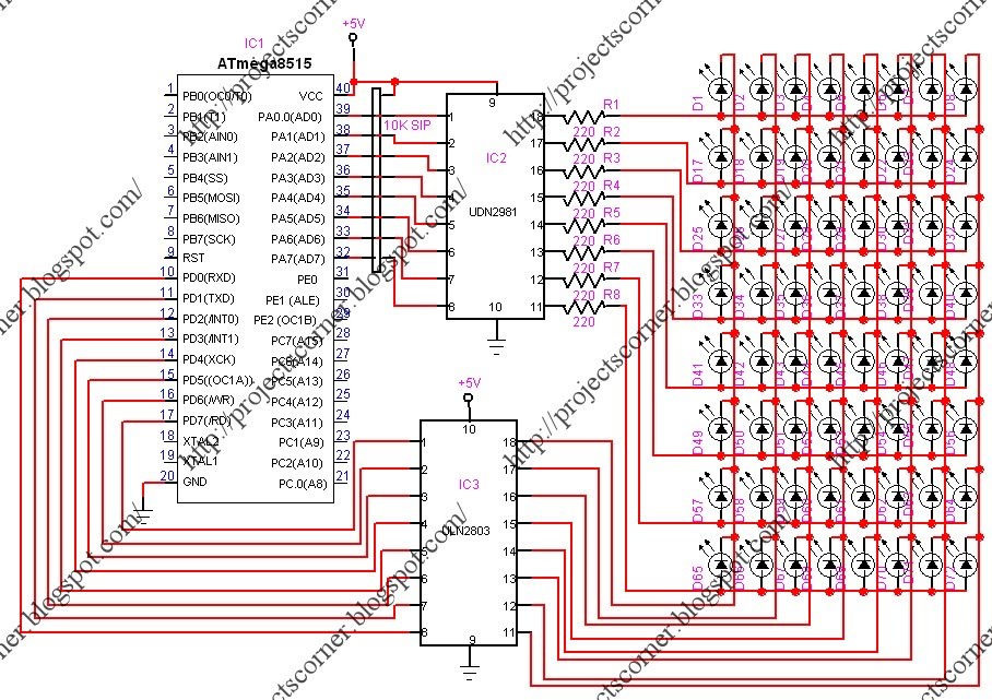
This project involves a scrolling LED display composed of 64 LEDs arranged in a matrix configuration. The anodes of the LEDs are driven by a driver IC, UDN2981, while the cathodes are controlled using the ULN2803. An Atmega8515 microcontroller...

This circuit utilizes a pair of Zener diodes to monitor the voltage of a 12-V battery. When the voltage drops below 11 V, diode D1 ceases to conduct, causing pin 3 of flip-flop IC2 to go high. This action...
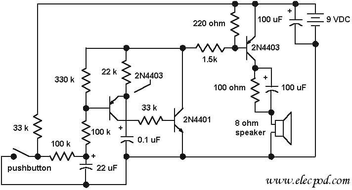
The core component of the circuit is a dual transistor flasher with frequency modulation applied to the base of the first transistor. When the pushbutton is pressed, the oscillation frequency increases to a peak, and when the button is...
The high and low voltage cut-off with delay and alarm circuit, along with its circuit diagram, is explained in this post. The high and low voltage cut-off circuit is designed to protect electrical devices from damage caused by excessive voltage...