
LED driven tail/brake Light Cluster

The described circuit serves as a control mechanism for a light-cluster composed of multiple light-emitting diodes (LEDs), intended for use in automotive applications as a tail and brake light. The circuit operates on a dual-state control system, utilizing two switches: SW1 and SW2.
In the normal operating state, when SW1 is closed (turned on), the light-cluster is powered at a medium brightness level. This is typically achieved through a resistor in series with the LED array, which limits the current flowing through the LEDs to prevent overheating and ensure longevity. The medium brightness setting is suitable for standard tail light operation, providing sufficient visibility while minimizing power consumption.
The circuit incorporates a second switch, SW2, which is activated when the vehicle's brake system is engaged. Closing SW2 allows for increased current flow to the LED cluster, resulting in maximum brightness. This is often accomplished by bypassing the resistor or using a relay that connects a lower resistance path to the LEDs, thus allowing a higher current to flow through, which is essential for signaling a braking action to trailing vehicles.
Protection measures, such as diodes, may be included in the circuit design to prevent back EMF from affecting the control circuit, particularly if inductive components are involved. Additionally, a fuse may be integrated to safeguard against overcurrent situations, ensuring that the circuit remains functional without damage during fault conditions.
Overall, this LED driver circuit effectively utilizes simple switch control to provide variable brightness levels, enhancing vehicle safety and compliance with automotive lighting regulations. Proper thermal management and component selection are critical in ensuring the reliability and performance of the light-cluster throughout its operational lifespan.This circuit was designed on request to drive a Light-cluster formed by several LEDs that can be mounted in the vehicle as a tail and brake light. When SW1 is on, the cluster will illuminate at medium brightness. When brakes are operated, SW2 will be closed and the cluster will shine at maximum brightness. 🔗 External reference
Related Circuits
Transistor Q1, a 2N3563, and its associated components form an oscillator circuit that will oscillate if, and only if, a good crystal is connected to the test clips. The output from the oscillator is then rectified by the 1N4148...
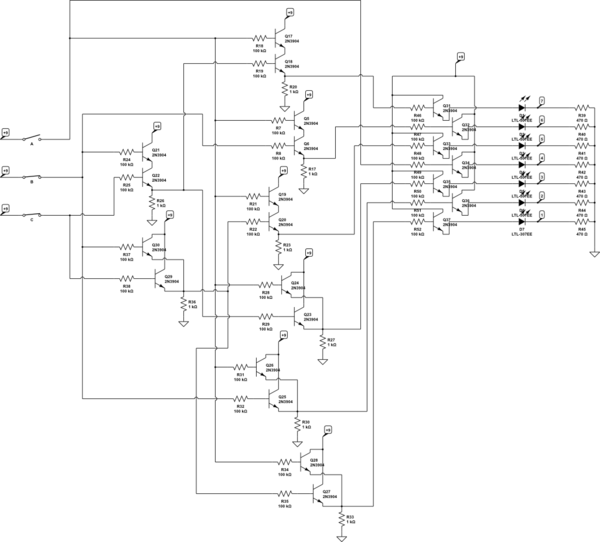
There are three switches that represent a binary number, and according to the combination of those switches, the number of lit LEDs changes to represent that binary number. There is a question regarding how to provide equal current and...

It is essential to ensure that none of the light bulbs on the vehicle are burnt out, particularly the turn signal lights, brake lights, and dashboard indicator lights. Malfunctions can occur when bulbs are burnt out. Utilizing the exterior...

This ultra-bright white LED lamp operates on 230V AC with minimal power consumption. It is suitable for illuminating VU meters, SWR meters, and similar applications. The ultra-bright white LED lamp designed for 230V AC operation offers significant advantages in terms...
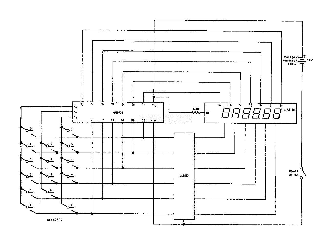
Configure the National Semiconductor DS8877 drive circuit as shown. When used with a 6-digit calculator and digital current conjunction, the current range is from 5 to 50 mA. The drive does not require standby power, and the operating voltage...
This emergency LED light is simple, inexpensive, and easy to build. The circuit connects to the battery, activating when the main power source is unavailable, such as during brownouts. White LEDs turn on automatically. Initially, the output voltage from...