
Led driver using LTM8042 ??Module Boost Driver

The LTM8042 LED driver is engineered to provide reliable constant current for LED applications while accommodating various dimming techniques. Its boost topology ensures that the output voltage can be higher than the input voltage, which is essential for driving multiple LEDs in series. The PWM dimming capability allows for precise control over brightness levels, making it suitable for applications requiring dynamic lighting effects. The analog dimming feature provides an alternative means of adjusting brightness, which can be advantageous in simpler designs or where PWM control is not feasible.
The circuit design using the LTM8042 is optimized for efficiency and simplicity. The essential components include input and output capacitors (Cin and Cout), which filter the input and output voltage respectively, ensuring stable operation. The Vcc capacitor (Cvcc) is used to decouple the internal circuitry of the IC, minimizing noise and improving performance. The design accommodates a range of input voltages, enabling flexibility in various applications, from battery-powered devices to fixed power supplies.
The ability to drive up to 9 white LEDs at 100 mA demonstrates the LTM8042's capability in high-performance lighting applications. The straightforward nature of the circuit allows for easy integration into existing designs, making it an attractive choice for engineers looking to implement LED drivers in new products. Overall, the LTM8042 LED driver IC stands out for its robust features, ease of use, and adaptability to different LED configurations and power requirements.LTM8042 combines a boost power topology with a unique current loop to operate as a constant-current source. The PWM input provides as much as 3000:1 LED dimming, while 10:1 analog dimming can be accomplished by a single resistor or analog voltage applied to the CTL pin.
The LTM8042 Led Driver IC is available in two types LTM8042 and LTM8042-1, th e difference between them is the maximum current supported which is up to 1 ampere for LTM8042 and up to 350mA for LTM8042-1. Both of these led driver circuits has an uninterrupted current path between its input and output and is thus intolerant to a short-circuit or overload from the output to ground.
The design of an circuit using the LTM8042 LED driver is very simple, requiring just few external components: Cin, Cout, Cvcc and in some casese few resistors. As you can see in the circuit diagram presented bellow this LED driver project has very few external components and is capable to drive up to 9 white LEDs at 100mA.
The input voltage required by this application is between 6 and 22 volts DC. 🔗 External reference
Related Circuits
A discussion took place on synth-diy regarding the challenges of constructing a voltage-controlled oscillator with a sawtooth wave output, where the duty cycle (the ratio of ramp-up time to ramp-down time) can be adjusted using a separate control voltage....
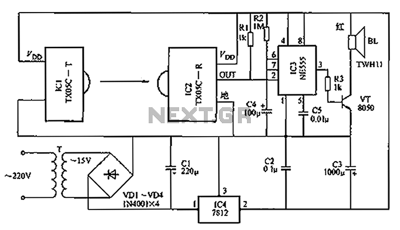
A new type of infrared system utilizes the TX05C radio sensor module for a burglar alarm designed for doors and windows. This system operates in the infrared spectrum, which is invisible to the human eye, making it suitable for...
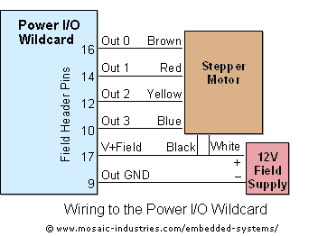
For optimal efficiency, set MAX_STEPPERS to the number of stepper motors being controlled, with a maximum limit of four. Motors are identified by indices 0, 1, 2, and 3. On the QCard, there is a trade-off between the number...
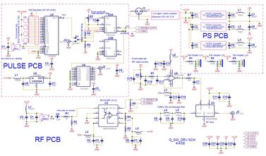
The Q-Switch driver for an old YAG laser failed. A replacement was over $1000, so a custom driver was built for less than $300 (see picture and schematic below). The specifications required were at least 20W into a 50-ohm...
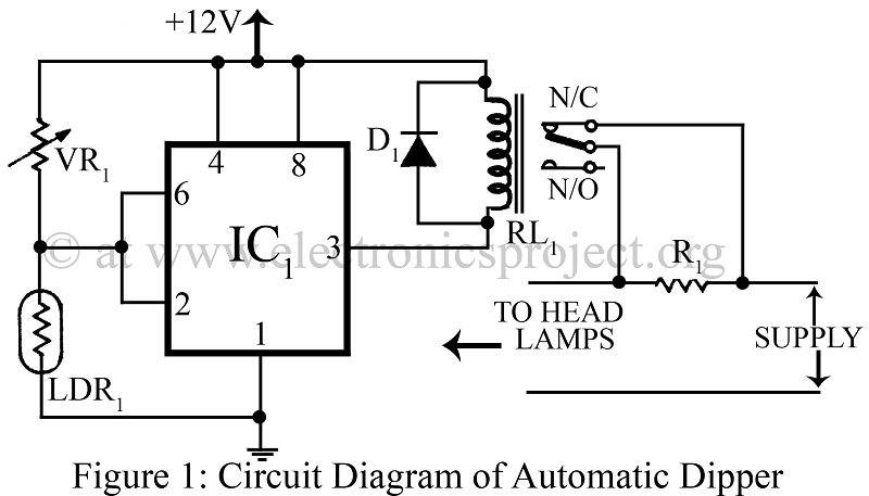
An automatic dipper for vehicles utilizing a timer IC NE555 and a light-dependent resistor (LDR) to control the headlight intensity of vehicles. This circuit diagram serves as a reference for various automobile projects. The automatic dipper circuit employs the NE555...
Measurement microphones differ from recording microphones and sound meters; they have a flat response (usually well below 20 Hz and above 20 kHz) and do not have a "weighted" or equalized frequency response. They are optimized for measuring high...