
Using the Panasonic WM61A as a Measurement Microphone
The schematic for interfacing the Panasonic WM61A Electret Microphone with the SoundBlaster CT4810 PC Sound Card should include a biasing network to ensure that the microphone operates within its optimal parameters. The typical configuration involves a resistor connected to the positive supply voltage (Vcc) and another resistor connected to ground, creating a voltage divider that provides the necessary bias for the electret microphone. The output of the microphone can be coupled to the sound card input through a capacitor to block any DC offset while allowing the AC audio signal to pass through.
The selection of the operational amplifier is crucial for achieving low noise and high fidelity in the audio signal. The LT1677, with its low input offset voltage and high common mode rejection ratio (CMRR), minimizes distortion and maintains signal integrity. It is advisable to use a power supply decoupling capacitor close to the power pins of the operational amplifier to reduce noise from the power supply and improve overall performance.
In addition, the layout of the circuit board should minimize the length of the signal traces to reduce the potential for electromagnetic interference (EMI). Ground planes should be used to provide a low-resistance return path for the signal and to shield sensitive components from noise.
Careful consideration should also be given to the enclosure of the microphone. The housing should be designed to minimize acoustic interference while protecting the components from environmental factors. The use of a windscreen or foam cover can further enhance the microphone's performance by reducing wind noise and plosive sounds during measurements.
Overall, the design of a measurement microphone using the Panasonic WM61A electret cartridge can yield an effective and low-cost solution for accurate sound intensity measurements across a wide frequency range.Measurement microphones differ from recording microphones and sound meters-they have a flat response, (usually to well below 20 Hz. , and above 20 kHz. , ) and do not have "weighted, " or equalized frequency response. They are also optimized for measuringhigh SPL sound intensity, (for example, measurements taken at fraction of an inch from a speaker driver-to
measure speaker response. ) Measurement microphones retail for US $100 to over US $500, but very adequate measurement microphones can be made using the Panasonic WM61A back electret microphone cartridge, which can be purchased through Digi-Key, part number P9925-ND, for under US $2. 00, each. Figure I, (which is available in larger size jpeg, or xfig, format, ) is a partial schematic for interfacing the Panasonic WM61A Electret Microphone cartridge to the SoundBlaster CT4810 PC Sound Card, including approximate signal voltage levels.
Figure II, (which is available in larger size jpeg, or xfig, format, ) shows the construction of a Measurement Microphone using the Panasonic WM61A Electret cartridge. The electret cartridge should be covered with silicon sealant, (I use GE`s Silicon II, Household Glue-which is available in the paint department of home improvement centers, ) taking special care that none of the sealant gets on the black cloth cover of the cartridge-the cartridge-to-case should be an air tight seal.
The wires should be soldered to the cartridge first, cut to length, and soldered to the plug-and the length checked by screwing the plug/cartridge into the casing, then the sealant applied, and the microphone assembled, (there are pictures, below, that show how to drill the hole for the cartridge, etc. ) The measurement microphone is specified at -35 dB +/- 4 dB, (0 dB = 1 V / Pa, ) with an load resistance of 2.
2K, and 1 Pa is 94 dB SPL, or 94 dB SPL produces 18 mV across the 2. 2K load resistance, (9 mV across two 2. 2K resistors in parallel = 1. 1K. ) Note: with a load resistance of two 2. 2K resistors in parallel, (or 1. 1K, ) and the tip and ring shorted, 100 dB SPL produced a measured 12. 7 mV signal at input to the sound card, which corresponded to, approximately, 0 dB FS. Figure III is a plot of the frequency response of a typical WM61A. Note that the unequalized response is flat to +/- 1. 5 dB to 20 kHz. However, there appears to be a zero in the transfer function at about 15 kHz. , (causing the response to be high by about 1 dB at 7. 5 kHz. , which could be canceled in the amplifier response to about 15 kHz. ) The microphone is quite good, (within its SPL limitations, ) and works well with the truly outstanding Baudline FFT time-frequency browser designed for scientific visualization of the spectral domain, and Xoscope, turning the PC into an audio analysis system. Ray Carlisle has developed a Spice circuit simulation model for the WM61A electret microphone using LTSpice, which is a free download from Linear Technology.
The simulations agree reasonably well with the empirical measurements on the microphone. Ruslan Migirov contacted the Panasonic corporation, and the FET part number for the Japanese version of the WM61A is 2SK123. For the US version of the WM61A, the FET part number is 2SK33720RLCT-ND. Figure IV, (which is available in larger size jpeg, or xfig, format, ) is the schematic of the amplifier for the Panasonic WM61A Electret Microphone.
Almost any operational amplifier will suffice since the JFET gain is quite high, (so amplifier noise is not a significant issue, ) but the Linear Technology LT1677 is a good choice because of its common mode input range, (allowing lower batter voltage and longer battery life, without running out of head space, ) with good noise performance, quiescent current requirements, single rail operation, and good 1/f noise characteristics. They are available on 🔗 External reference
Related Circuits
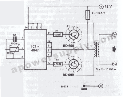
The inverter circuit features the CMOS 4047 as its primary component, converting a 12V DC voltage to a 220V AC voltage. The 4047 operates as an astable multivibrator. A symmetrical rectangular signal is generated at pins 10 and 11,...
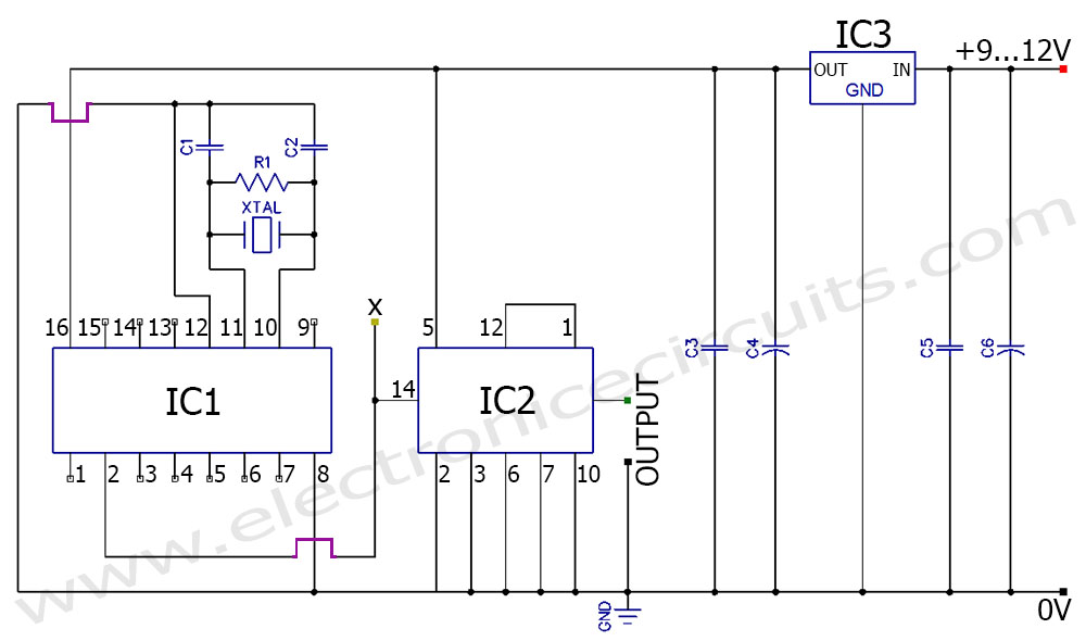
A frequency generator circuit capable of producing 50 Hz and 60 Hz outputs using a crystal oscillator. This oscillator can be utilized to generate precise frequency signals. This frequency generator circuit employs a crystal oscillator as its core component, which...
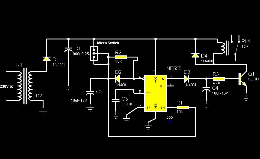
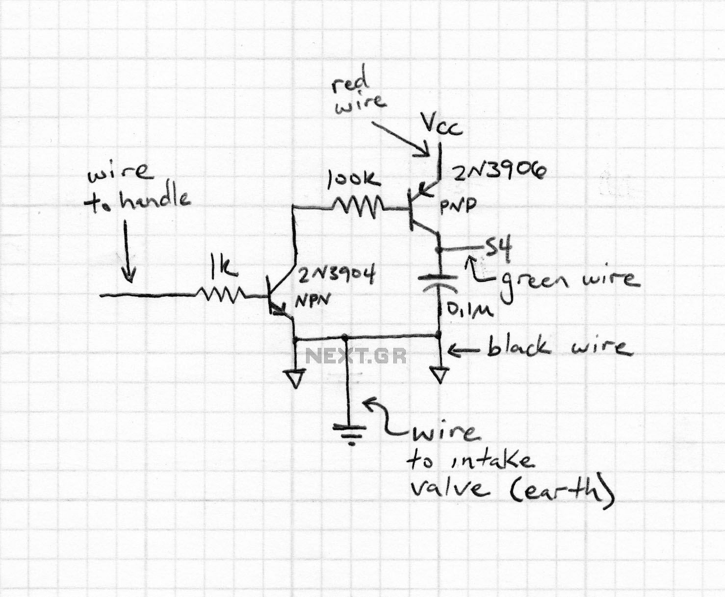
The circuit diagram illustrates a rotation sensor that activates a device, such as a motor or buzzer, when the circuit assembly is rotated. The design is based on the fundamental operation of a 555 timer. The rotation sensor circuit utilizes...

This application note discusses the use of SEPIC power modules to supply the necessary power for driving high-brightness LED arrays. These arrays serve as display backlights and necessitate a wide dimming range. The SEPIC configuration offers an efficient and...
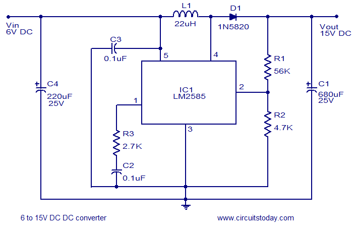
A simple and efficient 6 to 15V boost/step-up DC to DC converter based on IC L2585. This voltage converter circuit requires few external components. The circuit utilizes the L2585 integrated circuit, which is designed for high-efficiency voltage boosting applications. The...
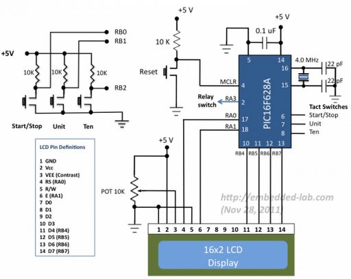
A source code for a simple PIC-based digital timer is provided. The hardware for the project is not available; however, it will be demonstrated using a DIY PIC16F628A breadboard module and I/O board. The complete circuit diagram and firmware...
Warning: include(partials/cookie-banner.php): Failed to open stream: Permission denied in /var/www/html/nextgr/view-circuit.php on line 713
Warning: include(): Failed opening 'partials/cookie-banner.php' for inclusion (include_path='.:/usr/share/php') in /var/www/html/nextgr/view-circuit.php on line 713