
led light circuit schematics

This circuit operates at a mains voltage of 220V, which is standard in many regions. Due to the high voltage involved, it is crucial that only those with sufficient expertise in electronics attempt to work with or modify this circuit. The design is likely to include components such as resistors, capacitors, and possibly transformers, which are essential for managing voltage levels and ensuring safe operation.
Safety precautions must be taken to prevent electrical shock. This includes using insulated tools, wearing appropriate personal protective equipment (PPE), and ensuring that the circuit is de-energized before any maintenance or modifications are performed. Additionally, the circuit should be housed in a secure enclosure to prevent accidental contact with live parts.
The schematic may involve a power supply section that converts AC mains voltage to a lower, more manageable voltage for the rest of the circuit. This could include a transformer to step down the voltage, followed by rectification and filtering stages to provide a stable DC output if required.
In summary, this circuit is intended for advanced users who are aware of the dangers associated with high voltage circuits and have the necessary skills to work safely with them. Proper safety measures and an understanding of the circuit's operation are essential to prevent accidents and ensure reliable performance.Do not try this circuit unless you have good knowledge about electronic devices. This circuit is connected to main power source (220V) and can give you a high electrical shock 🔗 External reference
Related Circuits
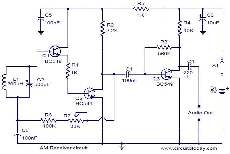
The following circuit illustrates an AM receiver capable of operating within the frequency range of 550 to 1100 KHz. Features include adjustments for sensitivity and selectivity of the circuit. The AM receiver circuit designed for the frequency range of 550...

The circuit diagram of a 7-segment counter circuit has been published here. This circuit consists of the counter IC CD4033 as its central component. The 7-segment counter circuit utilizing the CD4033 integrated circuit (IC) is designed to display decimal digits...

This circuit utilizes a pair of Zener diodes to monitor the voltage of a 12-V battery. When the voltage drops below 11 V, diode D1 ceases to conduct, causing pin 3 of flip-flop IC2 to go high. This action...
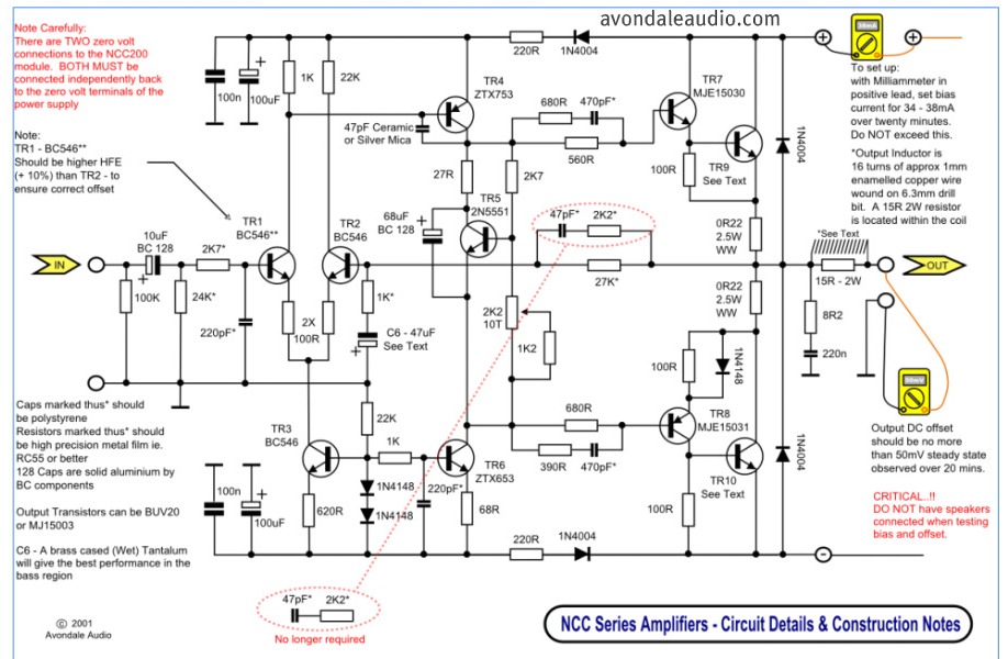
This is a simple circuit that features high-performance power amplifiers. The power amplifier is available as a PCB, along with a complete list of components. The described circuit utilizes high-performance power amplifiers, which are essential for applications requiring significant signal...
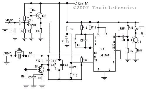
This small circuit transmitter processes audio signals from a sound table or microphone, as well as video signals from a camera, DVD, or video cassette. It has a composite video output, allowing direct transmission from a computer over a...
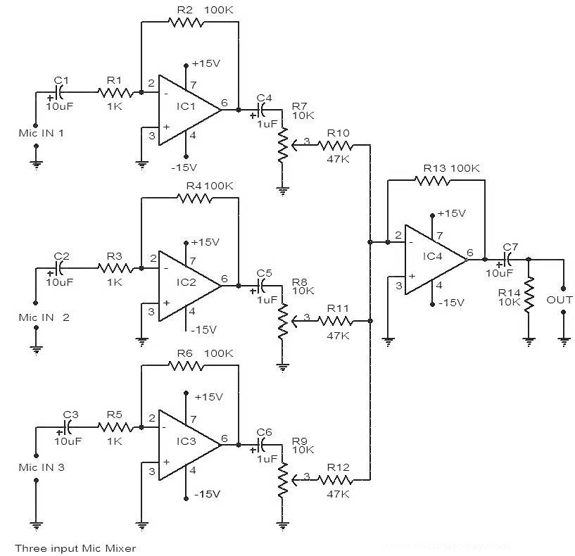
This is a circuit diagram of a 741 IC-based three-input microphone mixer circuit. A total of four 741 ICs are utilized, with IC1, IC2, and IC3 serving specific functions within the design. The circuit utilizes four operational amplifiers from the...