
Laser Controlled ON - OFF Switch

The circuit leverages the 555 timer IC, which is a versatile and widely used component in various electronic applications. The 555 timer can be configured in different modes, such as astable, monostable, and bistable. In this particular design, it is likely configured in astable mode, allowing it to function as an oscillator that generates a square wave output.
The basic components required for this circuit typically include the 555 timer IC, resistors, capacitors, and a power supply. The resistors set the charge and discharge times of the timing capacitor, which ultimately determines the frequency and duty cycle of the output waveform. The capacitor is charged and discharged through the resistors, creating the oscillating behavior characteristic of the astable configuration.
In practical applications, this circuit can be used for generating clock pulses, LED flashers, or tone generation in audio circuits. The output from the 555 timer can drive other components, such as transistors or relays, allowing for further control of larger loads or more complex functions.
The design's simplicity makes it an excellent project for educational purposes, as it provides insight into the operation of timers and oscillators in electronic circuits. Additionally, variations of this circuit can be explored by adjusting component values or configurations, leading to a deeper understanding of frequency modulation and timing applications in electronics.This circuit is built around a 555 timer using very few components. Since the circuit is very simple, even a novice can easily build it and use it as a co.. 🔗 External reference
Related Circuits
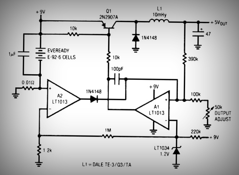
This circuit is a simple battery-powered switching regulator that provides a 5V output from a 9V source with 80% efficiency and a 50 mA output capability. When Q1 is on, its collector voltage increases, causing current to flow through...
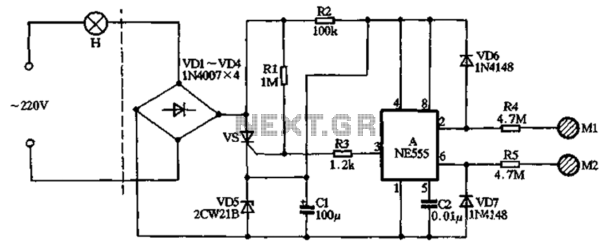
The circuit illustrated in the figure features a dashed line on the left, representing a standard lighting circuit, while the right side is responsible for the dual functionality of touch activation using the NE555 timer. Components VD1 through VD4...
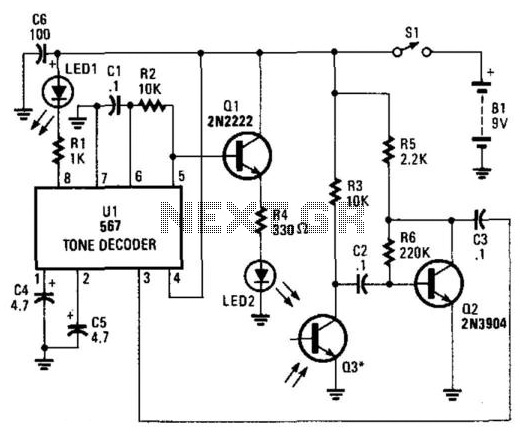
IR radiation from LED2, modulated by a 1-kHz wave, is activated by Ul, and Ql emits the radiation. Reflected IR energy is detected by Q3, and the audio signal from Q3 is amplified by Q2 before being sent to...
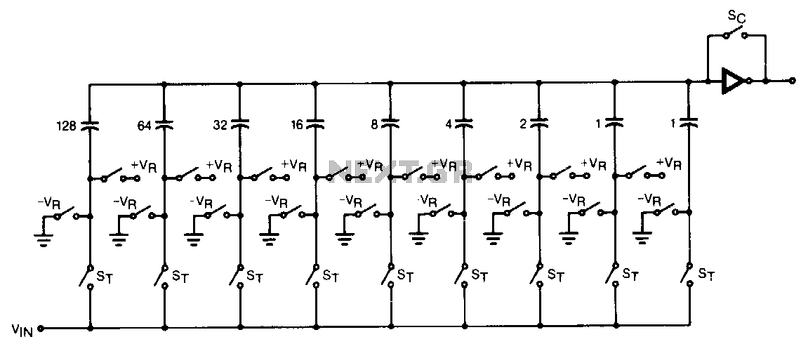
The CMOS comparator in the successive-approximation system determines each bit by examining the charge on a series of binary-weighted capacitors. In the first phase of the conversion process, the analog input is sampled by closing switch SC and all...
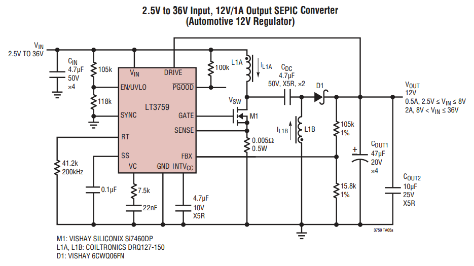
When VOUT is very low during startup or in the event of a short-circuit fault at the output, the switching regulator must operate at low duty cycles to keep the power switch current within the current limit range. This...
This light sensor switch circuit enables the automatic activation of a lamp when ambient light levels decrease, such as during nightfall. The duration for which the lamp remains on can be adjusted using potentiometer P1, with a range of...