
Wet soil tester with LED

P1 = 4.7 kOhm
D1 = LED
T1 = 547 BC
The circuit described operates as a moisture sensor that utilizes a simple transistor switch configuration to indicate the moisture level in soil or similar substrates. The two probes act as the sensing elements that detect the moisture content by measuring the resistance of the material between them.
When the probes are inserted into wet soil, the moisture provides a conductive path, resulting in low resistance. This low resistance condition causes the base of the NPN transistor (T1, 547 BC) to be at a lower potential, which keeps the transistor in the cutoff region. Consequently, the LED (D1) does not light up, indicating that the soil is sufficiently moist.
Conversely, when the soil dries out, the resistance between the probes increases significantly. This higher resistance leads to a more positive voltage at the base of the transistor, turning it on and allowing current to flow from the collector to the emitter. As a result, the LED lights up, providing a visual indication that the soil is dry.
The potentiometer (P1, 4.7 kOhm) is used to calibrate the sensitivity of the circuit. By adjusting P1, the threshold at which the LED turns on or off can be fine-tuned based on the specific moisture levels desired. This adjustment is crucial for ensuring accurate readings, particularly in varying soil types or conditions.
The circuit's simplicity makes it an effective solution for gardeners and horticulturists looking to monitor soil moisture without the need for complex electronic components. The use of a standard transistor and LED allows for easy assembly and minimal power consumption, making it suitable for battery-operated applications.This is a very simple circuit that can be used to test whether a pot is dry or not. When the two probes are inserted in wet soil, then the resistance between the sensors are low. The base of T1 will therefore be more negative and the LED is not lit. However, when the soil is dry, its resistance will be high and will base more positive. Then the LED Ured with the two probes at a damp cloth held. P1 is then adjusted so that the LED just goes out. P1 = 4.7 kOhm D1 = LED T1 = 547 BC 🔗 External reference
Related Circuits
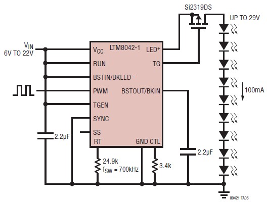
The LTM8042 integrates a boost power topology with a unique current loop to function as a constant-current source. The PWM input allows for LED dimming ratios of up to 3000:1, while analog dimming can be achieved with a single...
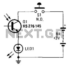
Using a battery, a phototransistor, and a visible-light LED, this simple circuit functions as a "go/no go" tester for infrared remote control devices. The illumination of the LED indicates that the phototransistor is being modulated by infrared energy. This circuit...
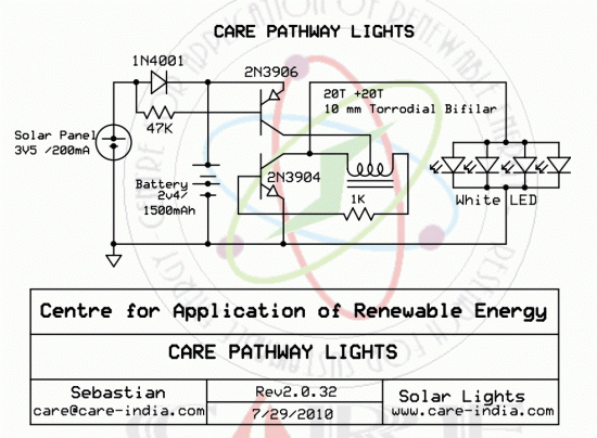
Simple pathway lighting that provides illumination for the path at night. Extension for the solar garden light. The toroid is bifilar wound. The described circuit involves a solar-powered pathway lighting system designed to illuminate walkways during nighttime. This system...

The Allegro A8732 is a Xenon photoflash charger integrated circuit (IC) specifically designed for ultra-low power, compact cameras, especially in mobile devices such as camera phones. It utilizes primary-side voltage sensing, which eliminates the need for a secondary-side resistive...

This is the second instructable focused on creating a digital watch as a learning experience. An Atmega644 chip from a Sanguino was available, which would have sufficed, but the intention was to burn an Arduino bootloader and test its...
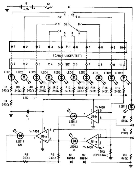
The cable tester utilizes two operational amplifiers (op-amps) configured as window comparators to detect short or open circuit conditions. A third op-amp comparator is employed to indicate a properly functioning circuit, meaning it is neither open nor shorted. Colored...