
led dot matrix display

To drive a dot matrix LED display, a common approach involves utilizing a microcontroller to control the individual LEDs. The display typically consists of rows and columns, where each LED can be turned on or off by energizing the appropriate row and column lines.
In the case of an 8x8 matrix, there are 8 rows and 8 columns, resulting in a total of 64 LEDs. Each LED in the matrix can be controlled by activating the corresponding row and column. For instance, if a specific LED located at row 3 and column 5 needs to be illuminated, the microcontroller would set row 3 to a high state while setting column 5 to a low state (or vice versa, depending on the common anode or common cathode configuration).
The circuit typically requires a few additional components, including current-limiting resistors to protect the LEDs from excessive current, and possibly multiplexing techniques to drive the display efficiently. Multiplexing involves lighting up one row at a time while quickly cycling through the rows, creating the illusion of a fully lit display due to persistence of vision.
For the 7x5 configuration, a similar method is employed, with adjustments made for the fewer number of LEDs. The microcontroller must be programmed to handle the specific number of rows and columns, ensuring that the correct LEDs are activated according to the desired display pattern.
In summary, driving a dot matrix LED display involves careful control of rows and columns using a microcontroller, along with additional components for current limiting and possibly multiplexing to achieve a functional and visually appealing display.How to drive an dot matrix led display. This project shows you how to drive one with 64 LEDs (8 rows by 8 columns) or less e.g. 35 LEDs (7 rows by 5 columns).. 🔗 External reference
Related Circuits
This may be the simplest LED flasher circuit you can build, with the notable exclusion of LEDs with integrated flashing circuits. This might be a good replacement for the LM3909 in some applications. Take a close look. Only the...

This circuit, designed on request, has proven to be useful to indicate when the voltage in a power supply line is changing from 120V to 240Vac. It can be used in different circumstances and circuits, mainly when an increase...
A common issue with small flashlights is the limited lifespan of both the batteries and the bulb. For example, a typical incandescent flashlight consumes approximately 2 Watts, while the LED flashlight shown in Fig. 1 consumes only 24 mW....

This is a simple circuit where an LED turns on only after a predetermined time once the power supply is activated. Initially, when the power supply is turned on, the transistor remains off. The capacitor charges through the preset...
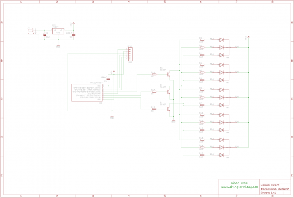
This project involves creating an RGB LED-lit love heart controlled by a PIC12F683 microcontroller. The design serves as a gift for a 15th wedding anniversary. The heart is crafted from a 200x150x6mm sheet of plexiglass, which is cut and...
Simple pathway lighting that provides illumination for the path at night. Extension for the solar garden light. The toroid is bifilar wound. The described circuit involves a solar-powered pathway lighting system designed to illuminate walkways during nighttime. This system...